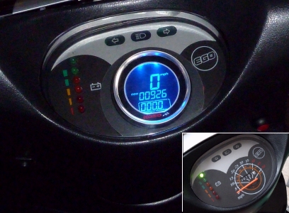
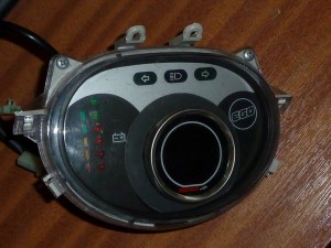
My new, digital speedometer and the old one (inset). A trip count reset button (red) has been installed to the right.
If you saw my recent post detailing my speedo driver problems, you might have been left with the impression that I was able to get mine fixed and back to normal. Unfortunately that wasn’t quite accurate. That little coupler that needed adjusting and putting back in after it failed the first time eventually gave out completely. At first it started making these horrible noises, which would come and go at random, then the speedo packed in again completely. It occurred to me again just how little of the life of the bike the speedometer had actually worked for: Out of the 3 years I’ve had the bike, I think it only worked for a year before it clapped out shortly after I’d installed the Lithium pack.
I decided then that it was time to rethink the problem, which was that the speedometer/odometer that came standard with the bike was an antiquated and cruddy piece of work that has well and truly had its day. I had considered a digital speedo before, but was put off by the sky-high prices many were asking for such devices. Though they are in principle no more complicated than a £10 watch or multimeter, some of the prices being asked for basic customisable units were pretty astronomical, which I put down to the niche nature of this market. In the end though, I managed to identify a suitable unit for a price that was within my budget. I ended up with a KOSO DL01s Speedometer, ordering one with the optional button-on-a-lead so it could be operated externally.
This unit has five wires, and one sealed cable. Two of the wires them are for a signal from a fuel level gauge, but it’s designed for fuel vehicle setups, and whatever is usually connected to ordinary fuel level instrumentation. That will have to wait for now, but a fuel gauge is not a problem any more because I finally have a working LVC (low voltage cutoff) system that gives me plenty of warning via the LVC alarm lights.
The other three wires are the ones that are particular importance – the black, the red, and the brown. Herein lay a slight problem: Since the designers assumed that all vehicles have a permanently available 12V power supply via the battery, it has been designed to have a small part of it ‘always on’, so that it knows that it doesn’t have to run a ‘bootup’ test sequence. However, the 12V system on electric bikes is not ‘always-on’. It needs the ignition key to be turned before the system gets its 12V. One way of dealing with this is simply cross-wiring the red and brown. This means that you always get the little test sequence when you switch the bike on, but it’s fairly brief and not much more than the sequence you get on the dashboard of many cars.
The unit runs off the standard 12V vehicle electrical system
One thing I could do, I thought, was take a wire directly off the Lithium pack at a series interval of approximately 12V. This would mean a choice between the third cell – with a 9.6-10.8V range – or the fourth cell – with a 12.8-14.4V range. The problem is, that the unit might be working on the assumption that the 12V it receives through either part of the circuit is the exact same voltage, as it would be both sources were from a single car or motorbike battery. However, my understanding of how these things work is limited, and I’ve decided not to risk damaging it by breaking any design assumptions they might have made. In my arrangement, these three wires are run to a male, two-way mini connector, with the brown and the red wired together and receiving input from the 12V system. The black, of course, goes to the ground of the electrical system.
The final cable was the sensor, which needs to be threaded down to the site of the brake calipers, where it then takes readings from magnets attached about the disc. More about that later…
Setting the Odometer
Another problem with many of these units is that you cannot set the odometer and thereby transfer your existing mileage across to the new unit. This is a predictable and understandable measure taken to prevent unscrupulous vendors from trying to mislead people over a vehicle’s mileage, however with a little bit of imagination, a cheap fan and some strong tape, it’s possibly to use a simple but effective, brute-force approach.
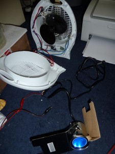
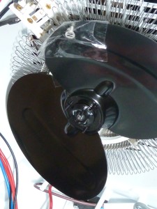
The magnet secured to a fan blade with strong tape
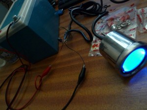
Above, you can see where I dismantled a fan and stuck one of the magnets onto the forward furthest facing part of the blade. After putting it back together, I now had a great way to quickly put miles onto my odometer! I wedged the probe into place between slats on the front of the fan, such that it was just a few millimetres away from the magnet. The speedometer had been set for the largest possible wheel size (about 2.5 metres circumference, or 80cm across), and so this arrangement gave me the fastest possible virtual speed.
There’s a short video clip of this setup in action here.
At the speedo’s highest sensitivity setting, the fan simulates a swift 210mph
After four hours or so at up to 210mph, the speedo had clocked up the amount of mileage logged by the existing, rubbish one that was about to be cut out, thrown away and replaced.
And just as evidence that the new speedometer now has more or less the same mileage as the existing clocks, here they are together once the speedo’s virtual journey is complete.
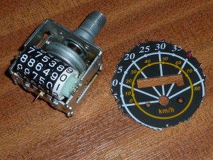
Thank you 19th Century, but we have better ways of storing digits now…
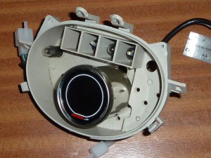
The next stage was to remove all the antiquated, clockwork junk comprising the old needle display, and then cut a hole custom-sized for the new unit, which was around 55mm at it’s neck. I couldn’t find a scroll saw with a thin enough blade, or that could really cut curves in metal, so I drilled lots of little holes in a circle of the diameter I wanted to cut out, then used some snippers/wire-cutters to cut between them, et voilà.
Bolts protrude from the back of the unit. and I drilled suitable spaced holes such that it could be secured to the plastic housing using the nuts provided.
Here it is assembled as a preview. As you can see, the hole that needed to be cut was quite jagged due to the lack of more expensive cutting tools, so I needed to make a cosmetic ‘collar’ from something that was more easily cutable.
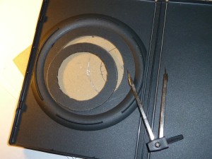
Eventually I realised that a matt DVD cover was almost perfect for the job. I used a stencil to cut a collar of the right dimensions.
And here it is partially reassembled with the collar in place. Much tidier, I think.
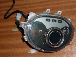
And finally, the display unit has been completely reassembled, complete with power connector, and is ready to go back on the bike.
The Sensor & magnets
So now I have the display all reconnected and wired in so that it will power up when I turn the ignition key. But there’s still the matter of the sensor and the magnets that it takes its readings from. The makers have come up with a clever way of using the mechanics of the brake disc and the brake caliper assembly to make it quite easy to fit the speedometer to pretty much any motorbike imaginable.
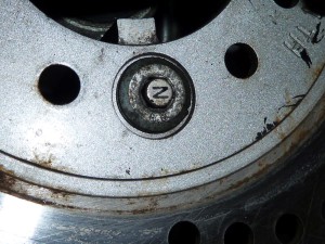
The brake disc is secured by a number of Allen bolts – on mine it’s three. You simply put the little magnets included into the sockets on the boltheads and that’s it! They’re held in place by just being magnets. The only thing you have to do is make sure the North pole (“N”) points outwards, to where the sensor will face.
The magnets sit in the heads of the Allen bolts that hold the brake disc on
Below, you can see the bracket and the sensor itself mounted by the front brake calipers. The bracket is secured in place using the same bolthole that secures the brake calipers. It’s finely adjustable, and needs to be set so that it passes over the magnet fairly close to it. I ended with mine about 5mm or so. The little electrical cable for the new sensor is secured by cable-ties to the hydraulic line running from the calipers up to the handlebars.
Below, you can see how the sensor is adjusted. A grub-screw in a recessed hole at the base of the bracket is tightened to secure the sensor – which can slide in and out – at just the right distance from the magnets on the brake disc.
The sensor position can be finely tuned
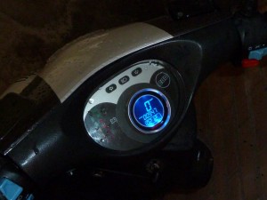
Up and running at last, complete with trip-counter reset button (see main picture at top)
Once I had the whole up and running, there was a certain amount of fine-tuning to be done. The unit needs to be programmed with a figure for the circumference of the wheel in milimetres, and the number of sensor magnets being used. Though I had both of these values calculated reasonably accurately, the speedometer was quite drastically out, reading about 40% of what it should. I ran past a roadside speed detector/display a couple of times, comparing my readout to that of the sign (someone else has my satnav at the moment) to help calibrate, and soon had it to within 5% or so, which will do for now.
One consequence of this upgrade is that you can now dispense with that cumbersome cable driver that goes with the regular, mechanical driver, and get rid of that big bracket that secures it to the bike. I find that the steering moves a bit more smoothly now without that cable clunking back and forth.








 Posted by Zenid