All Zephyred Up

April 30, 2015

P2 (Large)

My souped up, 80V ‘Ego Scoota’ nearly 5 years on and still going strong

Those of you who have been following my blog might be wondering where I’ve gotten to. It’s not often I keep the bike off-road over the winter, but with the repairs to the BMS, the expired MOT (inspection certificate) and the horrible weather I decided put the bike aside for a while to focus on work and other things that needed seeing to.

Now that the nice weather has returned, I’ve put the bike back together and started breaking in the fresh cells in the rebuilt pack. The perspex that I had screwed onto both sides of the pack had become quite broken up, and needed replacing too. Using little screws to secure the perspex to some of those little orange pegs on the cell holder seemed like a good idea at the time, but stresses from the less-than-even road surfaces I have to contend with daily were making the pegs break off and wearing away at the covers, breaking bits off and sending cracks through them. It was also fiddly having to undo a lot of tiny screws every time I needed to do something to the pack.


Li19 [1600x1200]

The 24s2p 76.8V nominal (86.4V charge) Lithium Pack

So now I’ve settled on a more basic arrangement. I replaced the perspex with fresh sheets, but just used clear packing tape to hold the sheets onto both sides. It’s not as pretty and elegant, but has the free play to deal with road vibration and will make servicing of the pack easier in future, though now I’ve got the LVC safeguards in place, cells will probably not need replacing for a good long time.

P1 (Large)

New perspex siding now just held on with strong packing tape

Breaking in the pack has been fairly routine. Because the new cells are out of balance with the others, the Zephyr goes into pulse mode at the end of a charge cycle, and needed keeping an eye on to make sure it didn’t get too hot. But three charge cycles in and it’s almost all balanced out again, with the EOC cutting off promptly with very little pulsing.

I was quit relieved about this, as I’d had to replace a few components on the Zephyr BMS after a weak cell died in mid charge and damaged one of the cell circuits (see last blog entry) something that could have been avoided if I’d been more careful and fixed it as soon as the warning light on the Zephyr LVC system started coming on. Though I was getting resistance readings on the newly repaired circuit  that were exactly the same as the other circuits, I couldn’t be sure all was well until I’d run it on the pack itself. Happily all appears well, the pack is more balanced, and it’s cutting off when it should do at the end of a charge cycle.

The bike has a new test certificate now so I’m finally back on the road, however some work will need doing to the bike soon: The terrible road surfaces, high speeds and a period of carrying 48Kg of SLA (lead-acid) batteries has taken its toll on the bearings of the steering column. There’s just a little bit of free play there, top and bottom, and so I’ll have to get this seen to before its next inspection.

72V36 [1600x1200]

72V23b [1600x1200]

The old arrangement, with six 12V SLA batteries

It’s proving impossible to get the specs for the runners and bearings needed for this bike, so I’m going to have to do it the expensive way and get a proper bike person to deal with this. Though I like to do whatever I can with my own hands, I’d rather leave the more technical mechanical stuff to a proper mechanic. Bearings are particularly important now with the bike being as powerful as it is, and I want to make sure it’s done properly with quality, ‘race standard’ parts.


Resistance is Futile

September 20, 2014

GRF04 (Custom)

Fried:  A cell dies during a charge and takes out a cell-circuit on the Battery Management System

The thing about Lithium cells is that they have to be treated with a certain amount of care and respect. You should get plenty of notice if cells are deteriorating. Weak cells throw the pack out of balance, taking longer to charge, and losing their charge more easily, lowering the capacity of the battery pack and the mileage you can get between charges. A while back, I finally got the cell-level LVC circuit of my Fechter Goodrum BMS up and working with my throttle and a warning light on my dash. If any cell goes below a certain threshold, a red warning light comes on permanently as an urgent alert to check my pack or give it a good charge. Since I typically recharge my pack well before it shows signs of flagging, I had hardly gotten to see it in action.

But one day when I was about to nip off to the supermarket I noticed that it was on. Checking the pack, I found that a slightly weak cell-pair had suddenly become a very weak cell-pair. This was one of the casualties from running the pack without an LVC system for so long, – I’d had to replace some cell-pairs when I’d run the pack almost flat a couple of times by accident (albeit over a 3 year span), but there was still one pair that was a little on the weak side but still serviceable.

So when the little red light came on  I was not entirely surprised, – the damage it had taken a couple of years earlier had finally caught up and the cell-pair was on its way out. If I’d been sensible, I’d have just pulled the pack there and then and taken the bike off the road, but I’d become quite dependent on the bike so thought I would run it a bit longer while I ordered a replacement pair of LiFePO4 cells.

Unfortunately, though, this isn’t such a good idea, as if you’re charging a pack and a cell-pair dies for good, this can result in damage to the BMS. So when, a couple of charges later, I noticed the charger was taking longer than usual, I should have unplugged everything sharpish rather than just leaving it to terminate of its own accord, which – in this case – meant turning the BMS’s corresponding cell-circuit turn into a giant fuse, burning most of its components to a crisp until the charger cut off automatically when it all shorted out. Taking the pack apart, the cells were clearly in quite a bad way.

GRF02 (Custom)

A very dead LiFePO4 38140S cell from my pack

The cells themselves weren’t really the issue here, though. The real problem was the blowback onto my beloved, home-built BMS. The main FET had initially born the brunt of it, burning itself to a crisp and leaving the big resistors on the back looking a bit ashen.

GRF03 (Custom)

The big resistors were still apparently alive, but given their condition (and the fact that they’re pretty cheap) I elected to replace them with other affected components. The capacitor here was also toast.

GRF04 (Custom)

The poor little 48.7KΩ and 220Ω resistors are almost totally destroyed. I think that as soon as the FET had burnt out and shorted, the power that would ordinarily be burned off as heat through the big resistors was channeled to the little resistors, which were pretty much totally destroyed. That – in turn – would have triggered the charger to shut down either via a signal from the BMS control circuitry, or the charger’s own safety cut-off. Either way, the charger checks out okay, so all I had to do was fix the circuit.

GRF05 (Custom)

Resistance is futile: Two of the 1/8W resistors are totally incinerated

My basic game plan for fixing the circuit was simple enough: Replace anything clearly burnt to a crisp, test other components and replace any obviously defective ones, then run resistance tests across the circuit until I got a result very similar to that across other cell circuits. One of the good things about these boards (Fechter Goodrum v4) is you really don’t need to know much about how they work to fix them: you can compare resistance meter and continuity readings between various bits of a dead circuit, and then compare those readings to any of the neighbouring circuits that are working. If you don’t get the same resistance readout across your circuit after replacing something, then just keep replacing things until you do!

So once my Mouser order was in for some spare cell-circuit components,  I went ahead and started replacing components. First, I switched the main FET and the two resistors. Next I pried out the incinerated little resistors and cleaned up the surrounding area with wire cloth.  I also took out the dead capacitor. For reference, here’s a little map of the components further down:

circuit


GRF06b (Custom)

I took the FAN431 next to the frazzled resistors out too, as well as the diode, then replaced the top diode and resistors with fresh ones.

GRF06d (Custom)

Next, in went a fresh FAN431.

GRF06e (Custom)

The 2906 transistor was shorted so I removed that and the 47Ω resistor next to it, which was also burned out. The TC54 transistor next to it came out too, since replacing all the the 2906 and all the other stuff still hadn’t restored the correct resistance readings for the circuit.

GRF07b (Custom)

With the 2906 and the TC54 transistor replaced I just had one problem: The 47Ω resistor was on back order, and not due in for another couple of weeks. Fortunately this didn’t affect my ability to test the circuit, I just temporarily stuck a larger 1/4W resistor of the same value into the holes to check the circuit. I’m getting all the right readings, now and it looks all ready for a proper test.  I just have to wait for that one little set of 47Ω 1/8W  resistors to arrive in the mail.

GFR08 (Custom)

All done, except for that one resistor

For anyone interested in joining the exciting world of homemade battery management systems, check out my thread for the Fechter Goodrum “Zephyr” 4.4 boards, which I also sell in my shop.  I’ve had mine for nearly four years now, and this is the first time I’ve managed to do any damage to it.

The take home message from this is of the stitch-in-time-saves-nine variety: There’s little point in having a great, cell-level, LVC system and battery monitor that warns you of weakening cells if you don’t heed the warning signs and red lights and keep chancing it with further recharges. Change weak cells sooner rather than later, don’t tempt fate by ignoring the warning signs of a dying cell-pair, and don’t continue to charge them until they die right in the middle of a charge cycle.


To PCB or not to PCB…

June 12, 2014

The batch of Fechter-Goodrum 4.4a Zephyr boards I had made back in November sold out a few weeks ago, and I’m getting enquiries from people who missed out on them. Unfortunately, though, I’ve been a bit short on cash, so can’t afford the outlay to get a fresh batch made.

All is not lost though; I’ve come up with a way round the problem: I’ve set up a pre-order system to help fund the outlay to get a batch of the new, 4.4b boards made. If you want one, just pre-order through the link at the shop. Once I have 6 pre-orders, I can afford to order the batch. The pre-orders will not include shipping – that will be taken care of when the boards are available and ready to ship. If I don’t get enough orders to fund a new run then I just issue refunds to whoever did pre-order. Worst case scenario is some wasted time. [Update: 4.4b boards available here]

GFZ3 (Custom)

NOW IN STOCK

So what’s so different about the 4.4b boards, then? A change requested by Richard Fechter – involving the addition of a component – has been made to the board, and there have also been a number of cosmetic changes:

1) A TVS diode has been added to offer an extra layer of protection for those dealing with banks running at higher voltages, such as configurations of 32s and above

2) Square pads have been added for the 47K capacitors, to prevent further confusion about which way round they go

3) Holes have been added to enable jump-wires to be soldered to save on redundant wiring where the top cell of one bank meets the bottom cell of the next. This allows a 24-pin connector to used for a 24s circuit, and so on

4) The component labels and values have been tidied up and moved to the silkscreen layer, where they’re easier to read.

4.4b TVS diode v2

The upgraded control circuit on the 4.4b version of the board

For those of you with 4.4a boards who think you might need the diode modification, you can easily ‘patch’ your existing board by adding the component as described on this Endless Sphere post.

As for my bike, there’s been nothing much to report recently. The bike and pack continue to work fine, and I typically get 15-20 around-town miles before the LVC system (the on-board, Fechter-Goodrum one, no less) starts to trigger the red, warning LEDs that tell me it’s time for a charge. So little to go wrong with these bikes once you’ve got them figured out. I am still on the look-out for a more powerful hub-motor, though, but I’m still finding it hard to come by ones more powerful than the 1500W one I already have.

If I can get hold of a 2000W one, and confirm from the weight that it’s probably more powerful than the one I already have now, then I’ll give it a go and see if I can get more performance. Have a great summer!


It’s Back! – The Fechter-Goodrum Zephyr v4.4a (‘Zenid Edition’)

November 14, 2013

GFZ3 (Custom)

It’s back! The Fechter-Goodrum 4.4 Zephyr board (now available here!)

It’s been nearly two years since Gary Goodrum and Richard Fechter made the controversial decision to put the welfare of their families before their obsession with exotic BMS designs, and suspended development of their now-famous BMS boards. Ever since they ceased trading, though, there’s been an unremitting stream of posts and queries asking after the boards and bemoaning the fact that they had pretty much ceased to exist.

Thanks to the wonders of cyberspace though, the designs were very much alive and well, and Richard Fechter seems more than happy to hand over the PCB cad file to anyone who was prepared to sink their own money into having some made. Challenge accepted! So after crowbarring open the proprietary ExpressPCB file format into a universal format that all PCB manufacturers use, I got a bearable quote and put through an order.

For those of you who haven’t heard about it, the Fechter-Goodrum v4.4 BMS is a cutting edge LiPo/LiFePO34 pack charging & balancing system that includes a built in, fully-featured, cell-level LVC/HVC system, with a throttle pass-through and various alarm connections. Naturally, the designers will get their cut of the profits once I’ve sold enough to break even. The margins are thin, but hopefully renewed interest in the units and a trickle of investment will keep the project moving forward or at least treading water until EV technology becomes more widespread.

GFZ2 (Custom)

So I’m the proud owner of a batch of the latest version of the Fechter-Goodrum Zephyr, version 4.4a. They’re almost identical to the one I used in the Zephyr unit I built, except the ones I ordered have a silkscreen print of the components to make it a little more user friendly (and pretty).

GFZ5 (Small)

Of course, I had to add my own personal touch, and “Zenid.com Edition” discretely adorns the edges of each 8-channel section.

So there you have it, folks. If you need a solid and dependable BMS/LVC system, and love to make things yourself, you might consider building one from the ground up. All the relevant parts lists and documentation can be found in the shop and on the Zephyr thread of Endless Sphere.


Fitting a Digital Speedometer/Odometer

October 2, 2013

DS01 (Custom) inset

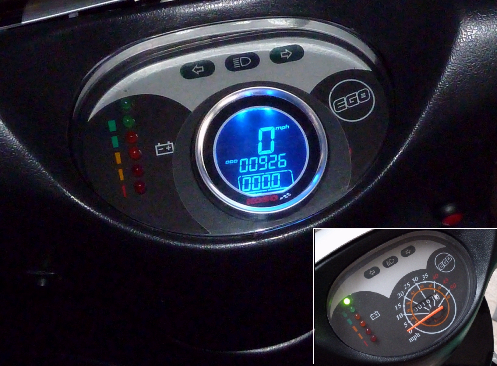
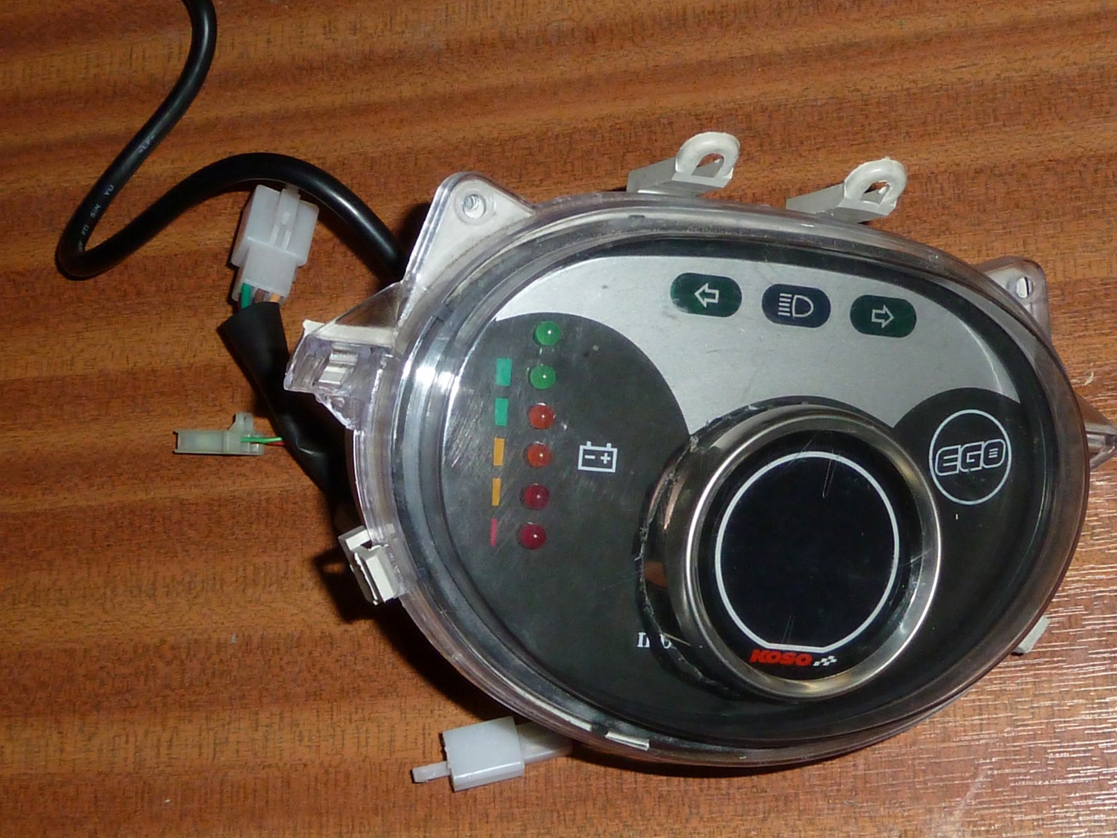
My new, digital speedometer and the old one (inset). A trip count reset button (red) has been installed to the right.

If you saw my recent post detailing my speedo driver problems, you might have been left with the impression that I was able to get mine fixed and back to normal. Unfortunately that wasn’t quite accurate. That little coupler that needed adjusting and putting back in after it failed the first time eventually gave out completely. At first it started making these horrible noises, which would come and go at random, then the speedo packed in again completely. It occurred to me again just how little of the life of the bike the speedometer had actually worked for: Out of the 3 years I’ve had the bike, I think it only worked for a year before it clapped out shortly after I’d installed the Lithium pack.

I decided then that it was time to rethink the problem, which was that the speedometer/odometer that came standard with the bike was an antiquated and cruddy piece of work that has well and truly had its day. I had considered a digital speedo before, but was put off by the sky-high prices many were asking for such devices. Though they are in principle no more complicated  than a £10 watch or multimeter, some of the prices being asked for basic customisable units were pretty astronomical, which I put down to the niche nature of this market. In the end though, I managed to identify a suitable unit for a price that was within my budget. I ended up with a KOSO DL01s Speedometer, ordering one with the optional button-on-a-lead so it could be operated externally.

DS02 (Custom)

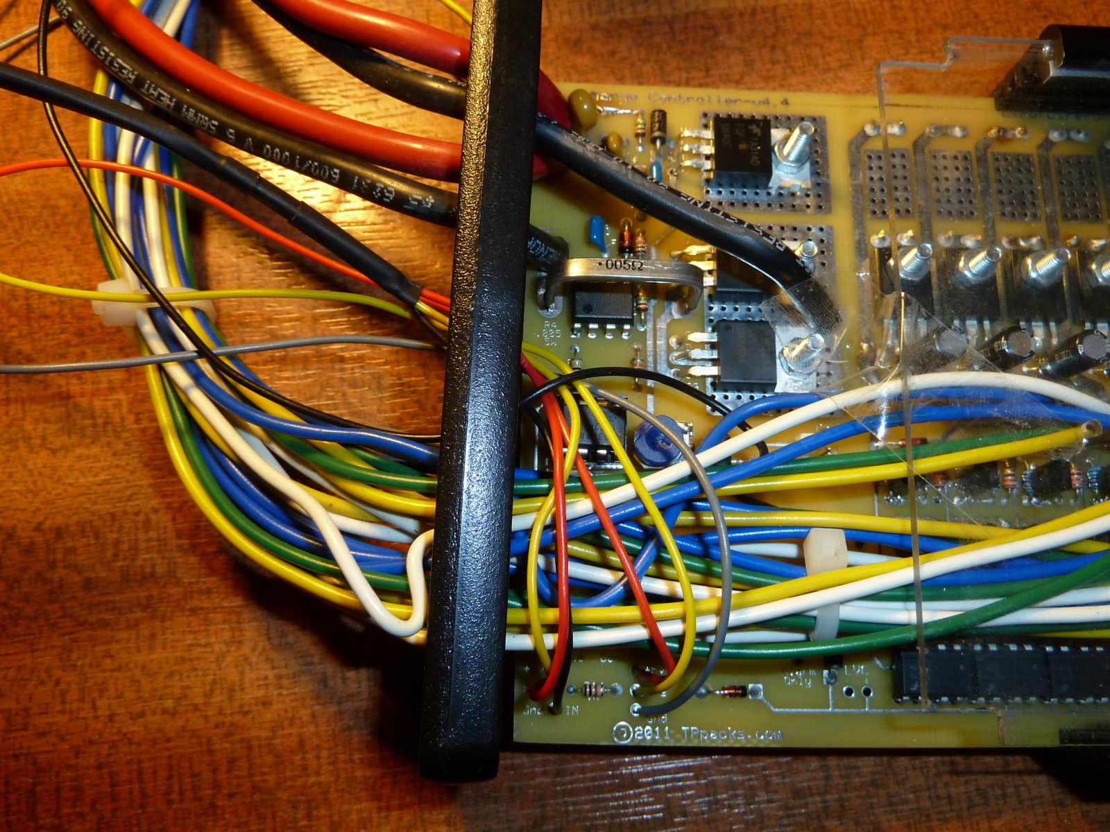
This unit has five wires, and one sealed cable. Two of the wires them are for a signal from a fuel level gauge, but it’s designed for fuel vehicle setups, and whatever is usually connected to ordinary fuel level instrumentation. That will have to wait for now, but a fuel gauge is not a problem any more because I finally have a working LVC (low voltage cutoff) system that gives me plenty of warning via the LVC alarm lights.

The other three wires are the ones that are particular importance – the black, the red, and the brown. Herein lay a slight problem: Since the designers assumed that all vehicles have a permanently available 12V power supply via the battery, it has been designed to have a small part of it ‘always on’, so that it knows that it doesn’t have to run a ‘bootup’ test sequence. However, the 12V system on electric bikes is not ‘always-on’. It needs the ignition key to be turned before the system gets its 12V. One way of dealing with this is simply cross-wiring the red and brown. This means that you always get the little test sequence when you switch the bike on, but it’s fairly brief and not much more than the sequence you get on the dashboard of many cars.

DS03 (Custom)

The unit runs off the standard 12V vehicle electrical system

One thing I could do, I thought, was take a wire directly off the Lithium pack at a series interval of approximately 12V. This would mean a choice between the third cell – with a 9.6-10.8V range – or the fourth cell – with a 12.8-14.4V range. The problem is, that the unit might be working on the assumption that the 12V it receives through either part of the circuit is the exact same voltage, as it would be both sources were from a single car or motorbike battery. However, my understanding of how these things work is limited, and I’ve decided not to risk damaging it by breaking any design assumptions they might have made. In my arrangement, these three wires are run to a  male, two-way mini connector, with the brown and the red wired together and receiving input from the 12V system. The black, of course, goes to the ground of the electrical system.

The final cable was the sensor, which needs to be threaded down to the site of the brake calipers, where it then takes readings from magnets attached about the disc. More about that later…

Setting the Odometer

Another problem with many of these units is that you cannot set the odometer and thereby transfer your existing mileage across to the new unit. This is a predictable and understandable measure taken to prevent unscrupulous vendors from trying to mislead people over a vehicle’s mileage, however with a little bit of imagination, a cheap fan and some strong tape, it’s possibly to use a simple but effective, brute-force approach.

DS06 (Custom)

DS05 (Custom)

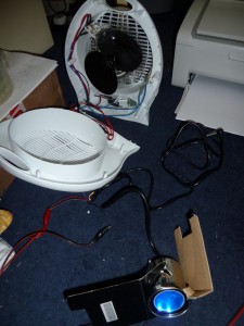
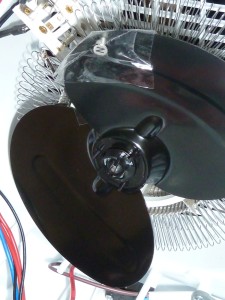
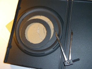
The magnet secured to a fan blade with strong tape

Above, you can see where I dismantled a fan and stuck one of the magnets onto the forward furthest facing part of the blade. After putting it back together, I now had a great way to quickly put miles onto my odometer! I wedged the probe into place between slats on the front of the fan, such that it was just a few millimetres away from the magnet. The speedometer had been set for the largest possible wheel size (about 2.5 metres circumference, or 80cm across), and so this arrangement gave me the fastest possible virtual speed.

DS08c (Custom)

There’s a short video clip of this setup in action here.

DS07 (Custom)

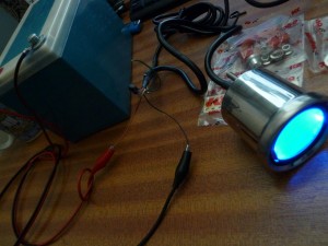
At the speedo’s highest sensitivity setting, the fan simulates a swift 210mph

After four hours or so at up to 210mph, the speedo had clocked up the amount of mileage logged by the existing, rubbish one that was about to be cut out, thrown away and replaced.

DS09 (Custom)

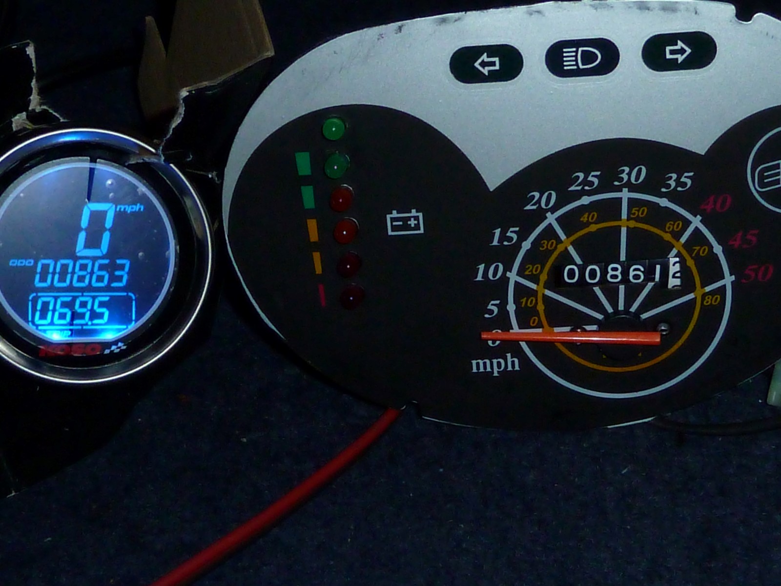
And just as evidence that the new speedometer now has more or less the same mileage as the existing clocks, here they are together once the speedo’s virtual journey is complete.

DS10b (Custom)

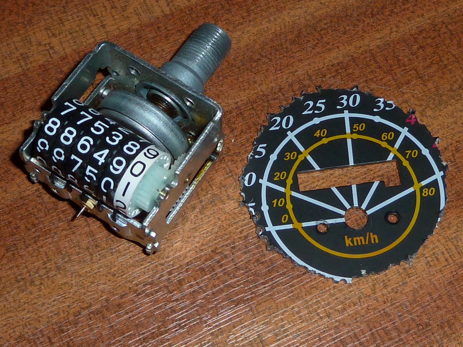
Thank you 19th Century, but we have better ways of storing digits now…

The next stage was to remove all the antiquated, clockwork junk comprising the old needle display, and then cut a hole custom-sized for the new unit, which was around 55mm at it’s neck. I couldn’t find a scroll saw with a thin enough blade, or that could really cut curves in metal, so I drilled lots of little holes in a circle of the diameter I wanted to cut out, then used some snippers/wire-cutters to cut between them, et voilà.

DS10 (Custom)

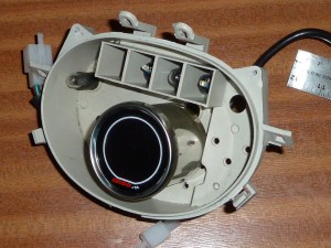
Bolts protrude from the back of the unit. and I drilled suitable spaced holes such that it could be secured to the plastic housing using the nuts provided.

DS11 (Custom)

Here it is assembled as a preview. As you can see, the hole that needed to be cut was quite jagged due to the lack of more expensive cutting tools, so I needed to make a cosmetic ‘collar’ from something that was more easily cutable.

DS12 (Custom)

Eventually I realised that a matt DVD cover was almost perfect for the job. I used a stencil to cut a collar of the right dimensions.

DS14b (Custom)

And here it is partially reassembled with the collar in place. Much tidier, I think.

DS15 (Custom)

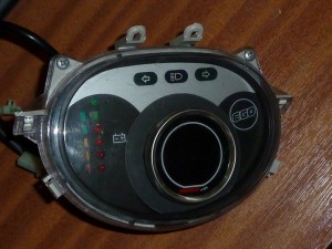
And finally, the display unit has been completely reassembled, complete with power connector, and is ready to go back on the bike.

The Sensor & magnets

So now I have the display all reconnected and wired in so that it will power up when I turn the ignition key. But there’s still the matter of the sensor and the magnets that it takes its readings from. The makers have come up with a clever way of using the mechanics of the brake disc and the brake caliper assembly to make it quite easy to fit the speedometer to pretty much any motorbike imaginable.

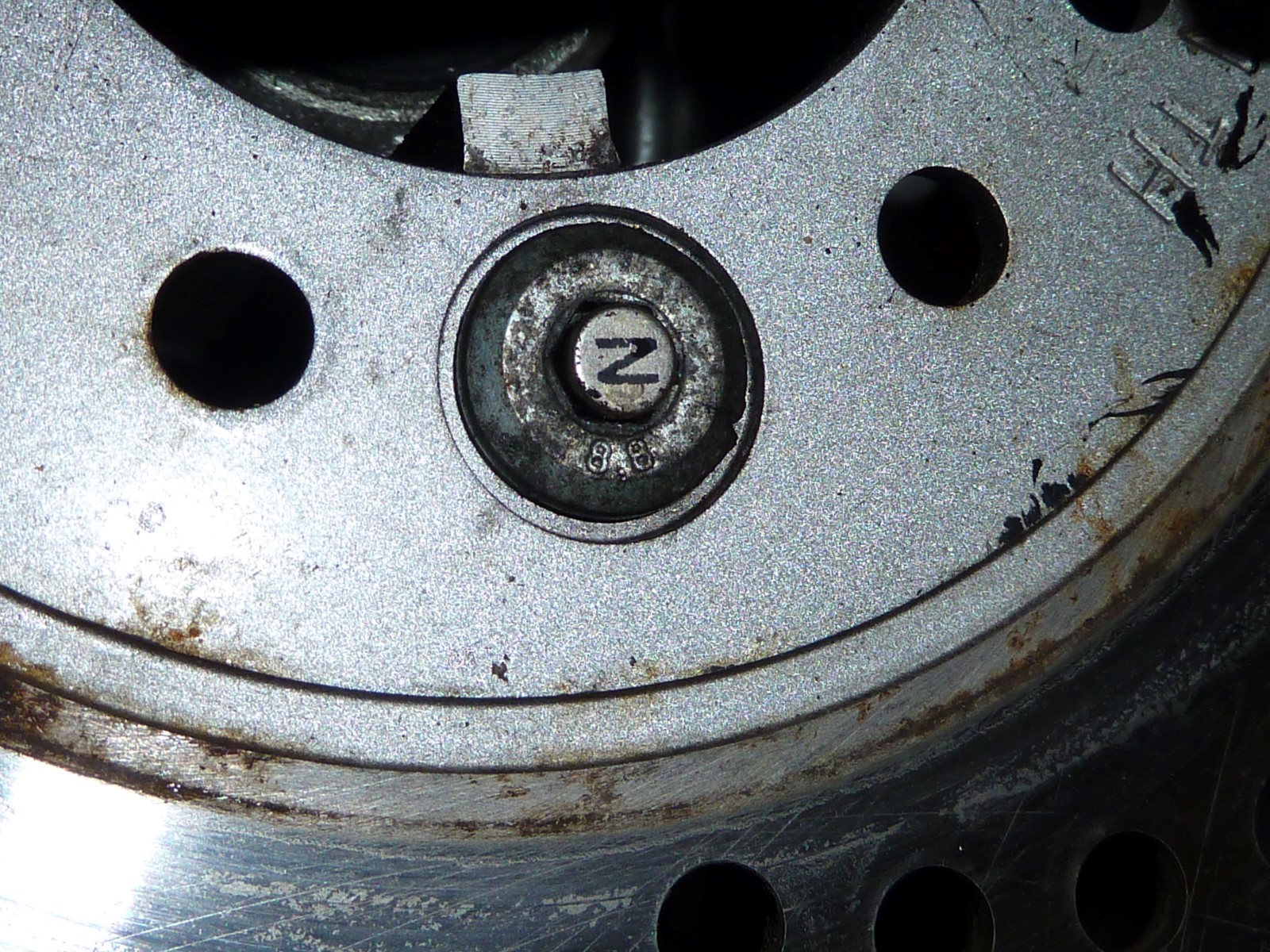
The brake disc is secured by a number of Allen bolts – on mine it’s three. You simply put the little magnets included into the sockets on the boltheads and that’s it! They’re held in place by just being magnets. The only thing you have to do is make sure the North pole (“N”) points outwards, to where the sensor will face.

DS16a (Custom)

The magnets sit in the heads of the Allen bolts that hold the brake disc on

Below, you can see the bracket and the sensor itself mounted by the front brake calipers. The bracket is secured in place using the same bolthole that secures the brake calipers. It’s finely adjustable, and needs to be set so that it passes over the magnet fairly close to it. I ended with mine about 5mm or so. The little electrical cable for the new sensor is secured by cable-ties to the hydraulic line running from the calipers up to the handlebars.

DS17d (Custom)

Below, you can see how the sensor is adjusted. A grub-screw in a recessed hole at the base of the bracket is tightened to secure the sensor – which can slide in and out – at just the right distance from the magnets on the brake disc.

DS17 (Custom)

The sensor position can be finely tuned

DS15b (Custom)

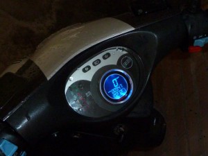
Up and running at last, complete with trip-counter reset button (see main picture at top)

Once I had the whole up and running, there was a certain amount of fine-tuning to be done. The unit needs to be programmed with a figure for the  circumference of the wheel in milimetres, and the number of sensor magnets being used. Though I had both of these values calculated reasonably accurately, the speedometer was quite drastically out, reading about 40% of what it should. I ran past a roadside speed detector/display a couple of times, comparing my readout to that of the sign (someone else has my satnav at the moment) to help calibrate, and soon had it to within 5% or so, which will do for now.

One consequence of this upgrade is that you can now dispense with that cumbersome cable driver that goes with the regular, mechanical driver, and get rid of that big bracket that secures it to the bike. I find that the steering moves a bit more smoothly now without that cable clunking back and forth.


Low Voltage Cutoff & Alarm System

September 29, 2013

LVC01 (Custom)

The LVC system of the Goodrum-Fechter BMS is finally wired up and working.

I’ve now finally gotten around to dealing with the LVC (low voltage cutoff) issues that I’ve occasionally mentioned over recent months. The Goodrum-Fechter BMS (that I’d built from the bare PCB and around 3,000 components!) also includes a dedicated LVC circuit that detects low voltage conditions for any cell in the pack, and enables action to be taken to prevent the cell in question being discharged low enough to do it permanent damage. The system includes a Low Voltage Cutoff Alarm, and a Throttle Modulator which acts on a pass-through for the throttle wires to go on their way from the throttle to the controller itself.

Once the voltage of any of the cells in the pack reaches a critical point (a little over 2.0V), the voltage across the LVC cutoff alarm terminals (see below) will rise quickly to 12V, where it will stay until the LVC condition is no longer met, and all cell voltages have returned above this threshold.

LVC01e (Custom)

In addition to these alarm terminals, there is also a pass-through for the throttle.

LVC02(Custom)

Here you can see the set of terminals for the throttle cable pass-through – the positive, the negative, and the signal wire. I’ve put a female 3-way mini connector on the “throttle in” wires, and a male 3-way mini connector on the controller-side wires. This arrangement makes it impossible to attach the throttle wires from the throttle, and the controller, throttle wires the wrong way round.

LVC05b (Custom)

The throttle pass-through lets the LVC system adjust the signal from the throttle as and when necessary. If any cell becomes dangerously low, the throttle signal will effectively cut out until the cell voltage has recovered. The effect of this is that as the battery pack power level declines, it will automatically ‘reign in’ any use of the throttle that’s severe enough to result in voltage dips as a result of heavy load on the battery. This is particularly prone to happen when power is drawn very rapidly, such as when taking off from a full stop or going up a particularly steep hill. In these circumstances, the LVC subtly modulates the throttle signal so that the lowest cell is protected from any voltage dips caused in this way, and acceleration eases off accordingly.

LVC06c (Custom)

Above, you can see the three cables I’ve added for the LVC system: The throttle pass-through (left, middle-bottom) and alarm signal (right).

LVC09 (Custom)

The connector linking the BMS pass-through to the controller throttle input cable

Once the BMS has been put back in position on the bike, I just detach the throttle from its direct connection with the controller, and clip both of those connectors into their counterparts on the BMS. The good thing about his system is that – if I really desperately need to get somewhere and am prepared to risk damage to cells in the pack – I can override the LVC system by just reconnecting the throttle directly to the controller again.

The second part of this system is the alarm I mentioned earlier. I ran the alarm terminals on the PCB to an external two-way mini connector, which I could then use to power whatever I want to be powered once the alarm-level voltage threshold has been tripped.

LVC08 (Custom)

I originally wanted this to run to a warning diode on my instrument display, but since it puts out 12V, it’s too much for a diode (which is limited to about 4V), I couldn’t do this in the way I’d originally envisaged. The battery meter upgrade that I’d done, and which was designed for the discharge characteristics of the old SLA bank, could not be used with my LiFePO4 Lithium Pack, and so was now just sitting there unused, with a row of 6 perfectly good LEDs on display. So I decided a temporary solution that was crude but effective: 12V was too much for just one LED, but if I linked 3 LEDs together in parallel they would be forced to “share” the 12V into 3 lots of 4V, which each LED can take okay. I could have just wired in a resistor but I liked this solution because I preferred to have more than one LED flashing for an LVC condition – just for the urgent look of it.

LVC08d (Custom)

Above you can see where I’m putting the LVC system to the test. The 12V alarm connector has been connected to a superbright LED, and the bank has been run down to the point where the alarm is easily triggered by opening up the throttle a little. Yes, I know that I just told you that LEDs only take about 4V, but it’s okay here because the LVC is just above threshold and I can just nudge the throttle open briefly so that I only get a brief burst of the alarm output and can see the LED flash or glow without frazzling it. In any case I have a bag of about 100 of these that I bought on impulse because of how cheap they were in bulk (about £6/$9 per 100!).

Using this method I was able to test it out an confirm that it did indeed give me the signal I wanted and when I wanted it. Now it was just a matter of running a cable to the instrument display.

But this also meant that I had to parallel wire three of my LEDs and run a two-way mini connector out of the back of the display to join with it (the alarm cable). In the end I decided to use the bottom three LEDs – one orange and two reds – as my alarm display.  While I was at it I put in a two-way mini connector for the top green LED as I currently had nothing showing on the instrument display to even indicate that I had the bike switched on! This time I just used a 100Ω resistor in series to drop the voltage within the range of the required 4V.

LVC11 (Custom)

The instrument display – You can just about make out my new, two-way connectors for alarm (left, green/red) and “bike on” (bottom, black/yellow) LEDs

LVC10 (Custom)

The alarm connector links to a cable that runs to the instrument display upfront

After putting it all back together again and going for a few rides where I ran the pack low, I got to see the fruits of my labours. As the pack started to get low, I would see the alarm lights just occasionally blink when I pulled away or went up a particularly steep bit of terrain, and this would steadily worsen until the three LEDs were constantly lit, albeit fairly dimly at first. At the same time, the throttle would become less and less responsive, and the motor would take on an odd note if I tried to pull the throttle fully open. Eventually, over the course of a mile or two, the bike would just get slower and slower, eventually grinding  to a halt with the three alarm LEDs fully lit (well lit, but not too brightly).

From the first warning winks of the alarm LEDs to when the bike finally ground to a halt was about five miles, which gives me more than enough warning, and plenty of time to get to a power socket to recharge.

So, finally, I have a reasonably foolproof LVC system that should protect me from damaging the cells of my battery by letting them get too low, as I have occasionally done over the last couple of years. This type of system is a must if you don’t want the headache of constantly checking cell voltages or removing the pack for servicing, not to mention the cost of replacement cells.


EMC-ya-later

September 8, 2013

emc3 (Custom)

Out with the old – my EMC-900 charger finally gives up the ghost

In my last blog I neglected to mention an unfortunate incident that happened while I was getting everything fixed and ready for the bike’s MOT inspection. I was in my kitchen (which looks out onto where I’d left my bike charging), when there was an almighty bang – like a firecracker going off – that came from the general direction of the bike. I went out to investigate, and straight away could smell the telltale odour of fried electronic components.

At first I was worried that it might have been my BMS (battery management system) that had failed. I had built it from scratch from a circuit board and around 3000 components (see the ‘Zephyr’ BMS build), and so it was irreplaceable, and I didn’t really fancy the prospect of taking it apart and diagnosing it, especially since it would probably mean hassling Richard Fechter, one of the designers of the BMS, for help fixing it. Fortunately though, the source of the explosion turned out to be my trusty (until that moment) EMC-900 charger, which was easily replaceable, though not especially cheap, especially with the £50 international shipping, and obscene import charges, taxes etc.

emc3 (Medium)

The blown MOSFET

Opening the charger, I soon found the source of the problem: A FET had exploded. I briefly considered trying to repair it by just replacing the component, but quite often when a component fails, other things also fail that aren’t so easy to track down and diagnose. Checking my BMSbattery account while I browsed around for a replacement, I noticed that I’d bought my charger 2 years and 3 months previously, so I couldn’t really complain about the service life I’d gotten out of it, especially since I’d been using it almost on a daily basis for months at a time.

Looking through the chargers available, it looked as though the EMC-900 had now been retired, however the more powerful EMC-1200 was available for just a little bit more, so I ordered one of those instead, speccing 85.6V and 11A output, with an anderson connector for the power output cable. Since the outside of the unit was identical to the EMC-900, it would also fit fine in the topbox I made for it, so that I could have it fixed to the bike if I needed to go anywhere I’d need a recharge to get back from.

Unfortunately, I’d forgotten to specify “50A” anderson, as I did with the old charger, so the one I ordered ended up with the piddling little connector below left. Fortunately, I had some 50A connector crimps lying around, so just salvaged the plastic connector bits from the old connector and transplanted the connector over to the new charger.

emc4 (Medium)

D’Oh! – Okay, so I forgot to specify the connector size, but then why didn’t they ask

Once up and running though, it worked fine, even cutting off the charge cycle at the exact 1.4A threshold that I’d had the BMS working at with the old charger. The model number (1200) is the power rating, 1200W, so theoretically it should be able to charge a third faster than my old, 900W version.

I’ve since upped the current setting to 12A using the adjustor pots (variable resistors) inside the unit, and it’s cut my recharge time from 2 hours 50 minutes (with the old charger) to just over 2 hours (from ‘flat’), and it looks like I might be able to up the amperage a little more if I really want to push it. Lithium packs can charge at an enormous rate, and my BMS is rated for 20A, so there’s plenty of scope to improve the recharge time further if needs be.

emc5 (Medium)

And in with the new – visibly almost identical, my brand new EMC-1200

Since I also had some weak cells in my LiFePO4 battery pack that needed replacing, I also ordered 6 new Headway 38140S 12Ah LiFePO4 cells plus a mass of the orange, plastic holders used to secure them (the legs on the holders can break easily when removing them to replace cells) and a few connecting plates . I only just recently got the LVC (low voltage cutoff) throttle and alarm circuits on my Zephyr BMS working, and so had still been relying on manual checks with my pack monitor to warn me of any dangerously low cells (more about that later).

Li1 [1600x1200]

Headway 38140S 12Ah LiFePO4 cells

Li2b [1600x1200]

The plastic holders and connecting plates

Without these proper safeguards, running it too far without a recharger would damage the weakest cells and let others get lower than they ought to as well. Hopefully, with the new LVC and alarm system in place, I won’t have to service the pack for a good, long time.


Speedo-Driver Problems

August 7, 2013

Image

The front wheel with axle and speedo-driver assembly removed

My bike has just celebrated its 3 year birthday, and with it, it’s now required to have an annual MOT inspection (UK), therefore much of the last couple of weeks was spent fixing a few things that needed doing to make it roadworthy. There was a broken weld on the centre-stand and a nail stuck in the back tyre. Most importantly, the speedometer hadn’t worked for a good while now, ever since the speed had first gone ‘off the clock’. I’d been putting the job off because it meant dismantling the instrument display to check on possible causes there.

The speedo works via a little driver attached to the axle by the front wheel (above right, and below). As the wheel rotates, this turns little cogs in the driver, that turns an impeller, which hooks into the base of the speedo cable. At first, I’d come to the conclusion that since spinning the wheel made the little impeller (the slot poking out of the speedo-driver) rotate, then the fault must be with the cable or behind the instrument display. The cable checked out fine, and oddly, so did the instrument display, so I backtracked to the speedo-driver again.

P1020577 [1600x1200]

The speedo-driver assembly (attached)

Image

Wheel with speedo-driver coupler removed

It turned out that though the impeller was indeed turning, any light resistance would make it slip. This slippage, it turned out, was due to a worn coupler. The piece – a bit like a bottle cap that fits in a recess at the centre of the wheel – anchors itself to points in the driver via a couple of little tabs at either side.

The tabs on mine were worn away and mashed-up looking, and no amount of bending them would make them engage. Eventually, though, a local bike shop found one identical that got me back in action for the MOT.

Image

The coupler to secure the speedo-driver assembly

A week later though, and the day before the MOT, the speedo failed again. It turns out that the tabs on this new one had gotten mashed down, so I plied them back up again as a repair. I’m not sure why it failed so quickly – maybe the relatively high speed of the bike, and the fact that the cable could do with some grease, resulted in it sticking as it rotated. I’m going to cover the whole length of the speedo cable in grease next, to see if that fixes it. I might also extent the tabs further up by sawing or slitting extra length for the tabs from the base. They don’t seem to go up far enough to make a firm connection with the driver assembly so a bit more bodging might be in order.

The good news, though, is that the bike got through its test just fine. A few days previously I’d had my local bike shop fix the tyre (I took tools with me and took the back wheel off myself), and so all I had to do was hope the speedo would last the duration of the test, which it did.  Despite my concerns (and others’) about my custom-built, LED headlights with their imitation, “dip-effect” function, there was no mention of this. Neither was there any quibble about the ever-so-slightly-too-small licence plate, either. He just tightened the rear brakes up a bit and left it at that. 🙂


Charge Point Success!

April 4, 2013

P1050069 [1600]

Success! My town now has a public charge point for electric vehicles

In early 2011, after I’d enthusiastically set about putting my bike through just about every possible upgrade, it soon dawned on me that provision for public charge points in the UK is pretty non-existent. Though they have a park-and-charge scheme in London, it is a struggle to find any public charge points anywhere else.

I met with my local MP (member of parliament), Sir Alan Meale to get some advice on how to go about getting more of these things available to the public and – as a campaigner with a long history of pursuing environmental issues – he had lots to say about what needs to be done to get more of this type of service put in place. The key, he said, was to target planning proposals for new developments and file an objection to plans for any car park that does not offer a charge point. Planning applications are posted in everybody’s local newspapers, and the process of local consultation is usually well organised, with council websites offering full electronic details of applications and plans, with the option offered for any members of the public offer their objections to any part of that development. These objections are all then addressed in a committee meeting between council officials and developers, with issues being discussed, and modifications being made to plans accordingly.

The big supermarket development

Practically every town in the country has some kind of big, commercial development in progress, with supermarkets like Tesco, Sainsbury and Aldi (here in the UK) rolling out huge new sell-it-all style warehoues of the kind we’re becoming increasingly accustomed to. The building spree of these growing commercial empires, though, offers perfect opportunities for electric motoring enthusiasts to take matters into their own hands by simply hunting down the relevant planning applications and complaining about lack of provision for motorcycles in general, and for electric vehicles specifically.

So when my MP reminded me of a massive, joint Sainsburys/Aldi development that was scheduled to replace a smaller existing Sainsbury’s, I did as he instructed and tracked down the plans for the development. The plans incorporated an impressive, 400 bay car park. So I formally filed an objection on the grounds that a) the parking development did not make adequate provision for motorcycles, and b) that no charge points were available for electric vehicles. I also wrote a letter to Sir Alan asking him to support my proposal for the plans to be amended to include these provisions, which he duly did, sending a letter to the committee dealing with the proposal.

I thought nothing more of it, and had totally forgotten about it when a few months ago a family member reported seeing a charge point in the new development.

P1050070 [1600]

Here it is! It’s activated by a little card that you get from staff in the supermarket. You wave the card across a little panel on the unit to release a flap on either side, each of which houses a regular, 240V power point. If you look closely at the picture you can make out a little display counting down 3 hours, which is the amount of time I’m allowed for a single ‘session’.

P1050073 [1600]

You can see the little green LED strip lit up indicating it’s live

Here you can see the charge point in action with my custom charger top-box. It just so happens that my bike will charge from flat in 2 hours 50 minutes, so 3 hours is more than I’ll need for a good top up while shopping.

P1050072 [1600]

So my little town is now host to the second of only two power points that exist within about a hundred miles of here!

Want one in your town too? If my story is any guide to how easy it is if you go through the proper channels, then all you have to do is a little homework, and some letter writing. These things aren’t going to just pop up all by themselves, YOU can get involved and be part of the electric motoring revolution. I appeal to all electric vehicle owners in the UK and elsewhere – both as motorcyclists and as electric vehicle enthusiasts – to actively seek out and file objections to local developments with “car” parks (just the fact that they are called “car” parks speaks volumes about the prevailing attitude towards motorcycles, any pedants here might also suggest that the authorities start referring to them as “parking areas”).

P1050071 [1600]

So please, folks, we CAN make a difference. If you want to see one of these in your local area, just do the following:

1) Check the planning applications in your local newspaper for anything promising a large car park. In particular, look out for a new commercial development housing a supermarket or big retail outlet

2) Go to the link given in the ad to file an objection. Write a polite and reasonable sounding request for provision for a charge point, and for better facilities for motorcycles and bicycles

3) Forward a copy of your request to your local MP asking him/her to support your application in writing.

A meeting is usually called to discuss the proposal, and the public is invited. I didn’t make it to mine, but it evidently didn’t make much of a difference.


Scooter Rebooted Pt. 2 – Heavy Duty Controller Heatsink

January 6, 2013

HS12 1600

A custom, copper heatsink and mount are bolted to the baseplate, extending it to the rear to accommodate the larger, 18-FET controller

Parts

  • 4 pieces of – 100 X 260mm 0.3mm copper sheet
  • 3 pieces of – 60 X 260mm 0.3mm copper sheet
  • One piece of – 60 X 220mm 3mm copper sheet
  • One piece of – 60 X 220mm 0.3mm copper sheet
  • 6 3.5mm countersunk head bolts

Having upgraded both the hub motor and the controller, I thought I’d take the opportunity to incorporate a custom heatsink into the rear mounting plate. The current 1500W hub motor is basically maxed out now, with the 16-FET controller more than enough to give it all it can take (about 4KW), so the controller doesn’t run very hot at the moment, but in order to clear an upgrade path for a more powerful hub motor, as well as address an issue with mounting controller that’s too big for the baseplate, I decided to design a heatsink custom made to maximise contact with the controller casing.

HS03 1600

Most controllers are either 180mm or 210mm from end-to-end of the baseplate. This one, though is 260mm, and as you can see from the picture above it overhangs the baseplate by 50mm or so. My solution to this was to build a heatsink that would also double as an extension for the baseplate. By stacking cut pieces of thin copper sheet of alternating width and bolting them firmly to the base, I get good wide fins that help with heat dissipation. The air being funnelled to the controller area, and the good thermal contact with the base plate should both help draw heat away from the controller.

HS02 1600

Below you can see stage one of the heatsink which acts as the main base for the controller.

HS04 1600

As any of you who have dabbled with controller will know, however, the controller casing has an odd recess underneath that prevents most of the controller case making good thermal contact. Only the brackets at the end, and a section of case running the length either side make contact with the baseplate when the controller is mounted. The recess is about 3.2mm, and I had two special pieces cut to act as a seat that would allow the base of the casing to make near-complete thermal contact with the heatsink.

Below you can see the main item, a 3mm thick slab of copper, and a thinner 0.3mm sheet of the same size that brings the plate almost flush with (actually about 0.1mm proud of) the controller base.

HS05 1600

The tricky bit in mounting this on top of the first stage of the heatsink is to do it in such a way that the heads of bolts are sunk so they are flush with the base of the controller case. Any bolt poking up will stop the case from making good thermal contact.

HS06 1600

After some fiddling with different drill bit sizes, and very gentle drilling I eventually ended up with a second stage plate with six suitably  recessed bolt holes.

HS07 1600

HS08 1600

Finally, six corresponding holes were drilled through the heatsink base sheets and the baseplate. From the underside, you can see both parts of the heatsink now firmly bolted to the baseplate. I cut off the excess lenghs of these bolts with a grinder. You can see how the heatsink adds the extra required length to the baseplate from below.

HS14 1600

The finished product! A nice big heatsink that doubles as a lengthened baseplate for the controller.

HS11 1600

HS12 1600

A final touch before mounting the controller was to remove some instructional stickers that were on the base. Thus, the aluminium of the base sits directly onto its heatsink mount.

HS13 1600

And there you have it. A solid heatsink that helps keep things running nice and cool. You can see a thermocouple I attached so I could monitor its performance. The most striking difference is that though the controller still gets warm when thrashed, it cools down much quicker, with the rate of cooling directly proportional to how hot it’s getting. Definitely a must for people who like to push their controllers to the limits.