Speedo-Driver Problems

August 7, 2013

Image

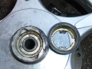
The front wheel with axle and speedo-driver assembly removed

My bike has just celebrated its 3 year birthday, and with it, it’s now required to have an annual MOT inspection (UK), therefore much of the last couple of weeks was spent fixing a few things that needed doing to make it roadworthy. There was a broken weld on the centre-stand and a nail stuck in the back tyre. Most importantly, the speedometer hadn’t worked for a good while now, ever since the speed had first gone ‘off the clock’. I’d been putting the job off because it meant dismantling the instrument display to check on possible causes there.

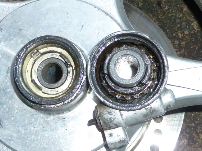
The speedo works via a little driver attached to the axle by the front wheel (above right, and below). As the wheel rotates, this turns little cogs in the driver, that turns an impeller, which hooks into the base of the speedo cable. At first, I’d come to the conclusion that since spinning the wheel made the little impeller (the slot poking out of the speedo-driver) rotate, then the fault must be with the cable or behind the instrument display. The cable checked out fine, and oddly, so did the instrument display, so I backtracked to the speedo-driver again.

P1020577 [1600x1200]

The speedo-driver assembly (attached)

Image

Wheel with speedo-driver coupler removed

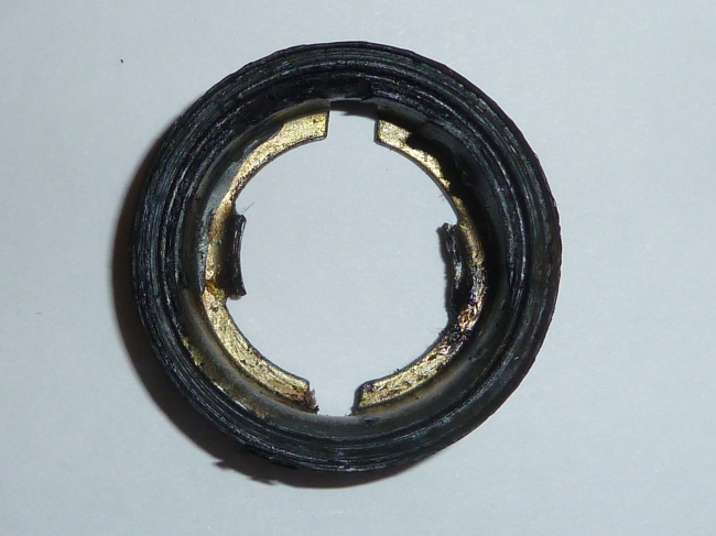
It turned out that though the impeller was indeed turning, any light resistance would make it slip. This slippage, it turned out, was due to a worn coupler. The piece – a bit like a bottle cap that fits in a recess at the centre of the wheel – anchors itself to points in the driver via a couple of little tabs at either side.

The tabs on mine were worn away and mashed-up looking, and no amount of bending them would make them engage. Eventually, though, a local bike shop found one identical that got me back in action for the MOT.

Image

The coupler to secure the speedo-driver assembly

A week later though, and the day before the MOT, the speedo failed again. It turns out that the tabs on this new one had gotten mashed down, so I plied them back up again as a repair. I’m not sure why it failed so quickly – maybe the relatively high speed of the bike, and the fact that the cable could do with some grease, resulted in it sticking as it rotated. I’m going to cover the whole length of the speedo cable in grease next, to see if that fixes it. I might also extent the tabs further up by sawing or slitting extra length for the tabs from the base. They don’t seem to go up far enough to make a firm connection with the driver assembly so a bit more bodging might be in order.

The good news, though, is that the bike got through its test just fine. A few days previously I’d had my local bike shop fix the tyre (I took tools with me and took the back wheel off myself), and so all I had to do was hope the speedo would last the duration of the test, which it did.  Despite my concerns (and others’) about my custom-built, LED headlights with their imitation, “dip-effect” function, there was no mention of this. Neither was there any quibble about the ever-so-slightly-too-small licence plate, either. He just tightened the rear brakes up a bit and left it at that. 🙂


Scooter Rebooted Pt. 2 – Heavy Duty Controller Heatsink

January 6, 2013

HS12 1600

A custom, copper heatsink and mount are bolted to the baseplate, extending it to the rear to accommodate the larger, 18-FET controller

Parts

  • 4 pieces of – 100 X 260mm 0.3mm copper sheet
  • 3 pieces of – 60 X 260mm 0.3mm copper sheet
  • One piece of – 60 X 220mm 3mm copper sheet
  • One piece of – 60 X 220mm 0.3mm copper sheet
  • 6 3.5mm countersunk head bolts

Having upgraded both the hub motor and the controller, I thought I’d take the opportunity to incorporate a custom heatsink into the rear mounting plate. The current 1500W hub motor is basically maxed out now, with the 16-FET controller more than enough to give it all it can take (about 4KW), so the controller doesn’t run very hot at the moment, but in order to clear an upgrade path for a more powerful hub motor, as well as address an issue with mounting controller that’s too big for the baseplate, I decided to design a heatsink custom made to maximise contact with the controller casing.

HS03 1600

Most controllers are either 180mm or 210mm from end-to-end of the baseplate. This one, though is 260mm, and as you can see from the picture above it overhangs the baseplate by 50mm or so. My solution to this was to build a heatsink that would also double as an extension for the baseplate. By stacking cut pieces of thin copper sheet of alternating width and bolting them firmly to the base, I get good wide fins that help with heat dissipation. The air being funnelled to the controller area, and the good thermal contact with the base plate should both help draw heat away from the controller.

HS02 1600

Below you can see stage one of the heatsink which acts as the main base for the controller.

HS04 1600

As any of you who have dabbled with controller will know, however, the controller casing has an odd recess underneath that prevents most of the controller case making good thermal contact. Only the brackets at the end, and a section of case running the length either side make contact with the baseplate when the controller is mounted. The recess is about 3.2mm, and I had two special pieces cut to act as a seat that would allow the base of the casing to make near-complete thermal contact with the heatsink.

Below you can see the main item, a 3mm thick slab of copper, and a thinner 0.3mm sheet of the same size that brings the plate almost flush with (actually about 0.1mm proud of) the controller base.

HS05 1600

The tricky bit in mounting this on top of the first stage of the heatsink is to do it in such a way that the heads of bolts are sunk so they are flush with the base of the controller case. Any bolt poking up will stop the case from making good thermal contact.

HS06 1600

After some fiddling with different drill bit sizes, and very gentle drilling I eventually ended up with a second stage plate with six suitably  recessed bolt holes.

HS07 1600

HS08 1600

Finally, six corresponding holes were drilled through the heatsink base sheets and the baseplate. From the underside, you can see both parts of the heatsink now firmly bolted to the baseplate. I cut off the excess lenghs of these bolts with a grinder. You can see how the heatsink adds the extra required length to the baseplate from below.

HS14 1600

The finished product! A nice big heatsink that doubles as a lengthened baseplate for the controller.

HS11 1600

HS12 1600

A final touch before mounting the controller was to remove some instructional stickers that were on the base. Thus, the aluminium of the base sits directly onto its heatsink mount.

HS13 1600

And there you have it. A solid heatsink that helps keep things running nice and cool. You can see a thermocouple I attached so I could monitor its performance. The most striking difference is that though the controller still gets warm when thrashed, it cools down much quicker, with the rate of cooling directly proportional to how hot it’s getting. Definitely a must for people who like to push their controllers to the limits.


Disassembling and Reassembling the Hub Motor

July 28, 2012

Removing the stator is quite easy, but getting the cover plate off can be a little more challenging

Introduction

The hub motor – like any motor – is made up of two main parts. The first part is an axle surrounded by a fixed ring of copper coils, called the stator. The second part is a housing into which the axle seated, and where it is allowed to rotate freely. This housing, which part of the rear wheel, is surrounded by a ring of strong magnets that surrounds the ring of coils connected to the axle. The hub motors used by most (but not all) electric bikes also have three ‘hall-effect’ sensors seated in a metal ring surrounding the coils, which relay signals back to the controller.

The phases wires that provide power to the motor and the thinner, sensor wires that feed back to the controller are all housed in a thick, insulated cable that runs through a hole in axle to the inside of the stator. To get access to the workings of the motor you need to remove the stator from the rear wheel, and – if necessary remove the cover plate so that the area inside the coils can be accessed.

1) Remove the bolts securing the stator

The stator is held onto the rear-wheel housing by a ring of allen bolts. A ratchet screwdriver with a suitable attachment will make short work of these. It’s a good idea to put them in a little baggy so you don’t lose any.
The

The stator cover – little alan bolts secure it to the wheel

2) Remove the drum brake assembly and push out the stator

First it’s best to remove the drum brake assembly from the other side of the wheel. You can see the drum brake assembly below. Remove the nut and washer from the end of the axle and the drum brake assembly, including the cover plate, lever and brake pads should just slide off in once piece.

The next bit requires a bit of force, but is quite straightforward. Even though the bolts are off, the stator is still held in place by powerful magnets, and needs a bit of encouragement to release. To remove the stator from the wheel, find a piece of wood and rest the wheel on top of it so that the end of the axle on the underside is firmly braced against the ground. Then push down firmly on both sides of the tyre. If it seems stuck, then put your knees on the tyre and bear down with all your weight. With enough force the stator will pop out and you’ll be able to remove it from the wheel.

Here it is removed. Towards the bottom, you can see the hall sensor wires where they meet the hall effect sensors embedded around the edge of the unit.

3) Remove the stator cover-plate

This is as far as you’ll need to go in taking the motor apart if all you need to do is replace a defective hall sensor, but if you need to repair damaged wiring (like on the unit here) or even replace the phase wires for something thicker then you’ll need to also get that cover plate off the stator.

The only thing holding the plate on is the friction between it and the axles’s bearing, however it’s a very tight fit and can’t easily be removed without specialist equipment. A hub-puller of the right size, or a hydraulic press can be used to push the axle through while the plate is held firmly. In the end I went to my local university’s mechanical engineering workshop, and they popped it off with a big hydraulic press.

Once removed, you can see where the cable emerges from the axle on the other side of the plate, and where short lengths of surplus phase wire are covered in nylon and tied back.

Below you can see the ends of the phase wires once released from the cable-ties and with the bits of nylon sheath removed.  You can see where they are joined to the ends of three thick, copper cables which run lead into the banks of coils surrounding the stator. Once you have access to this part, you can make any repairs to damaged wires, or even replace the thinner phase wires that come with some hub motors with thicker grade wiring that can carry more power.

4) Reassembly

The stator cover

Though the cover plate for the stator may be quite tough to remove, it’s usually a lot easier to get back on. In my case, some gentle help using a wooden-headed mallet was enough to get the cover plate back over the bearing.

Replacing the stator

As for putting the stator assembly back into the wheel, this needs to be done with a certain amount of care, as once the stator is far enough into the rear wheel housing, the magnets will slam the stator back into place quite firmly, so MIND YOUR FINGERS!

You will also need to bear in mind that the stator needs to be properly aligned so that all the holes in the case meet up with those in the housing. If not you’ll have to remove and reseat it again until it’s properly aligned. To help with this, I poked a screwdriver through on of the holes in the case and its corresponding hole in the housing so that the stator slid into place reasonably well aligned. Once the stator was in place, I replaced the bolts, diagonally from one another and eventy spaced, tightening them up alternately to ensure that the stator went back in properly aligned.


Testing the Hub Motor

July 21, 2012

Though hub motors tend to be fairly well behaved and can run for years without problems, they do occasionally go wrong. If the bike suddenly stops working or develops problems, you often end up in a position where you need to find out if it’s the controller or the motor that’s at fault.

Many enthusiasts who’ve done a lot of tinkering with their bikes usually end up with at least one spare controller lying around, in which case it’s just a case of swapping it out to see if that fixes the problem. Most people, however, do not have spares available and may need to do some specific testing to rule out any issues with the motor.

1) Access the Phase Wires and Hall Connector

The first thing to do is to remove the seat to get access to the junction where the phase wires are connected (bottom) and the hall connector socket can be found (top left). The phase wires are the three, thick blue, green and yellow wires. The hall sensor wires are five thin wires: black, red, blue, green and yellow that run from the motor cable to a 6-way mini-connector. On some bikes the phase wires are part of a plug instead, in which case you’ll have to adapt your test accordingly. For this test you will need to detach the phase wires on the motor side from the connection block so that they are isolated from the controller. Leave the hall connector connected, though.

Phase wires and Hall Connector

The phase wires are the wires that provide power to the motor, magnetising sequences of coils that generate the rotational motion. The hall sensors are three little transistor-like devices embedded along the inside edge of the motor, which send information about the motor movement back to the controller.

2) Test the Phase Wires

First, with the bike on its stand (and the bike switched off), test that the rear wheel spins freely. If it doesn’t you most likely have a short between the phase wires, though this is rare. The next thing to do is to remove the phase wires from the block and short them one pair at a time (e.g: yellow/green, green/blue, blue/yellow). As you hold them shorted together, try turning the wheel again. This time, you should find resistance. If you don’t get resistance when any pair of wires is shorted, then there is a break somewhere between the phase wire and the motor.

Phase wires and hall connector, detached

3) Test the Hall Sensors

For the next test keep the phase wires disconnected but make sure that they are kept properly separated. Preferably put a bit of insulation tape on the ends to prevent mishaps. Again, keep the hall connector connected.

Next, you will need to turn the ignition on, and take voltage readings from the wires in the hall connector. Since the connector is plugged in, you will need to access it from the rear, sticking the multimeter probes into the recesses and touching the crimps holding the wires in place.

The hall sensor wires

Take voltage readings across the black wire and – in turn – the blue, green and yellow wires with the back wheel turning slowly. It’s best to get someone to help out with turning the wheel for this part, while you take readings. As the wheel turns, the signal should flip between 0V and about 4.5V, at a rate of about 23 cycles per rotation of the wheel. If you get this reading from each of the wires, then all is well, otherwise, you have a blown hall sensor and will need to open the motor to replace it.

If you have a bit of pocket money spare, and want to make life easier, you could invest in one of these very handy motor/controller tester gadgets that will do it all for you. You just plug in the hall connector, attach clips to the phase wires, and the blinky lights give you the answers straight away! The controller-tester part of the unit, however, is only compatible with controllers up to 60V, though, so it can test the motor – but not the controller –  if you have a 72V system.


Replacing a Hall Sensor

July 12, 2012

Hall effect sensors sometimes fail, but are easy enough to fix

Taking the hub motor apart and replacing a hall sensor might sound like a pretty daunting task, but it’s really not that difficult. The first thing you need to do is get hold of a suitable, replacement SS41 hall-effect sensor. One can usually be found on ebay here, or from RS components (but with a pretty steep postage price) here.

Next you remove the stator (the hub motor section of the rear wheel) from the rear wheel itself (see blog entry) so that you can get at the motor’s inner workings. This done, the hall sensors and wiring are exposed and ready to work on.

The sensors are held in little shaped grooves in the metal treads on one side of the stator’s perimeter. Now you need to identify which sensor holds the wire that you detected a fault on. Each sensor has three wires, – two of them are the 4.5V live (red) and GND (black) which serve the sensor, the third is the hall sensor wire which returns a signal to the controller based on its rotational position in the hub motor casing. The third wire for each hall sensor is yellow, green and blue respectively, as shown below.

In my case, it was the yellow wire that was showing no signal, and this one goes to the middle hall sensor on my stator.

The component itself is held in with a bit of epoxy resin and sometimes has bits of silicone sealant gummed about. The epoxy can be softened by warming it a little with the flame from a cigarette lighter.

A gentle tap with a hammer and screwdriver knocks it loose with ease.

Note how one side of the hall effect sensor has bevelled corners. This side faces outwards (on my motor, at least) and is designed so that it can only fit in its socket the right way round. This is important, as it makes it hard to accidentally reverse the wiring sequence.

Here’s the replacement sensor in situ.

You can more clearly here how it fits with the bevelled corners facing outwards.

Next it’s a simple case of soldering the new sensor in. Snip the head of the old sensor off, strip the hall sensor wires, and desolder the legs from the old one, then solder on the legs of the replacement sensor. Don’t forget to put fresh sections of heatshrink on the wires, and push them way up the wires where the soldering iron won’t prematurely shrink them. Then pull the heatshrink down into place over the soldered legs, like with their neighbours.

This done, it’s a case of fitting the sensor back into its socket. Use a little blob of epoxy resin to hold it firmly in place.

All done! Finally, carefully refit the stator to the rear wheel and test the wiring from the hall connector. If you did everything right, then you should once more have a working hub motor.


Monitoring Pack Cell Voltages

September 5, 2011

… and a chance for a proper range test

N.B:  The CellLog 8M is now available from my shop. Due to import duty and small order size, this batch aren’t as cheap as I’d like, but if they sell well, I’ll get a better deal with a larger volume supplier and get the price down a bit more.

The Lithium pack monitor and LVC alarm

Now that I had my bike up and running with its Lithium pack, I needed some way of monitoring the pack voltages at the cell level. It’s imperative with Lithium cells that they are not discharged (or charged) beyond a certain level, or they can be irreparably damaged.

So far I had just been winging it by charging the pack regularly so that it was in no danger of being depleted to the point where this kind of damaged might occur. I’d also been running over the 24 pins of the battery pack’s ATX connector with a multimeter to take voltages and check that everything was okay.

Checking voltages in this way is immensely tedious, however, so I was quite keen to come up with a better way of seeing the state of my pack at-a-glance, and also having some way triggering an alarm or cutoff once cells dropped below a certain voltage.

One product that fits the bill for this job are the CellLogs. These handy little devices can monitor pack voltages for battery banks of up to 8 cells. They are fully programmable, and can be configured to set off an audible alarm or trigger an internal relay that can be tapped via an external connector.

The CellLog 8M (illustration from the EPBuddy website)

Wiring the CellLogs to the ATX connector

The CellLogs, unfortunately do not yet come in 24s form, so I had to improvise here by connecting three of them together to create a basic display which monitored my cell pack as three separate 8-cell banks. Later on I might remove the plastic casings and mount them more tidily in a single display that I can put somewhere on the bike on or near the instrument panel.

The final product, 3 CellLogs wired to the ATX connector and an earth wire

I wired the packs up to my ATX connector in much the same way as I wired up the BMS. Like with the BMS board, there are three 8-circuit modules which take 9 wires apiece. As with the BMS, the ‘top’ wire of each CellLog shares and pin on the connector with the ‘bottom’ wire of the previous bank. Since my ATX connector deals with the positive terminal of each of my 24 cells, the very first, master negative terminal of the first CellLog needs to be earthed somewhere. In this case I’ve simply connect this to an earthed connecting wire under the seat by the battery pack.

The CellLogs in action

The CellLog has a number of useful display screens which you can switch between, but the most useful one generally is the histogram display mode which gives you an at-glance-summary of the pack. The total pack voltage, the voltages of the highest and lowest cells and difference (‘delta’) between the lowest and highest cell in the pack.

Bank 1, almost perfectly balanced

Bank 2, not quite as perfectly balanced

Another screen gives you precise voltages for each cell in the pack.

Lots of things can result in packs becoming slightly out of balance. Immediately after charging, for example, cell voltages drop slightly as the cells settle, and this drop may happen at different rates. After the bank has sat for a while, though, the voltages tend to even out of their own accord.

Bank 1 of my pack as it settles shortly after charging

Prolonged use, especially when the bank is running low, can also lead the pack going out of balance. These imbalances, though, also tend to even out of their own accord once the bike has had a while to rest. Since the cells are always connected they have a natural tendency to ‘pull’ on another’s voltages back into alignment by themselves.

CellLog Alarm Settings

The great thing about the CellLog is that it can be programmed in a variety of ways to raise an audible alarm warning or to trigger an internal relay according to whatever criteria you decide. You can set high voltage and low voltage alarms for either (or both) the cell and pack-level voltages. Default settings also exist for the pack ‘delta’, where a difference between highest and lowest cell voltages will also trigger an alarm. The CellLog comes with default settings for typical LiPo and LiFePO4 settings, but you can add your custom ones in addition to these if you want.

As well as triggering an audible alarm (you can disable this if you want), it will also act as a relay to complete a circuit between two wires supported by a connector for the alarm port. It can be configured to be in either the ‘open’ or ‘closed’ position by default, and to switch to its opposing state once the alarm is triggered, and the circuit can accept a voltage of up to 50V at 500mA. For the purposes of the scooter, it would be suitable to wire into the 12V electrics to trigger a warning indicator that could be mounted on the dash. I have yet to do this yet. For now I’m just relying on regular visual checks of the cellog display.

The alarm port with its configurable relay can be tapped via an included connector

The Range Test

Now that I had a way of monitoring my cell-voltages, and an alarm system that would warn me of the collapse in the level of any individual cell, I was ready to put the pack properly through its paces with a range test. Here, I would basically run the bank ‘flat’, or – more precisely – to the lowest safe voltage that is recommended for the Headway LiFePO4 cells. It’s generally accepted that setting an lvc of 2.5V gives a cut-off point that preserves battery life and gives the pack up to 2000 or so charge-discharge cycles. You can of course take it lower, to around 2.0V, but now you’re on shakier ground where you risk upsetting a cell’s chemistry. If you let a cell’s voltage get below 1.7V or so then you can say goodbye to it forever, as it will almost certainly be irreparably damaged. Opinion is divided about how low is ‘safe’, but if you want the pack to have a decent lifespan it’s best to keep the voltages as far within the cell’s safe operating range as possible.

For my first range test I logged a total of nine journeys of  between 1.6 and 6 miles, which took place over the course of three days. For accuracy, I charted my journeys using google maps and noted the distance I had covered. I started out, of course, on a full charge. Though the charge voltage I use is around 86V, the voltage drops by a couple of volts as the cells settle once the charge is complete. Once rested a typical full charge of my pack shows a resting voltage of around 84V.

Just over ten miles into my series of trips, the pack voltage was looking good, with all three banks fairly well balanced. The voltage at this point was 80.1V. I left the bike to rest for a while before taking measurements, as the voltage always recovers a little after use. Any cell imbalances tend to gradually subside as well.

At 10 miles – pack voltage 80.1V

As I approached the 20 miles mark, performance started to feel a little more sluggish. A little like the tail-off you get with and SLA bank, but much later in the discharge cycle and far less pronounced. It became clear to me at this point that under any ordinary circumstances there’s no realistic prospect of unknowingly running down a cell to a dangerously low level as the performance of the bike is significantly affected well in advance of this.

Below is the state of affairs at 25.4 miles. Unlike SLAs, the LiFePO4 pack spends much of its discharge cycle well above the nominal voltage. As it descends through down past its ‘nominal’ voltage (76.8V for my 24s pack) the cell voltages begin to collapse almost exponentially. Though the pack voltage was still 76.55V, here, the cells were starting to go out of balance, with those closer to the positive terminal of the pack being worst affected. See how the ‘delta’ gets worse through banks 1 to 3.

At 25.4 miles, pack voltage 76.55V

Performance at this stage was also getting very bad, with the bike losing a good proportion of its power. At just past 26.9 miles I called it a day and hobbled back home to take a final measurement of a pack that was for all intents and purposes well and truly flat.

At about 27 miles the bank is effectively flat – pack voltage 73.35V

Bank 3 here us faring the worst, with the two weekest cells appraching their sub-2.5V danger zone. The pack delta at this point is nearly half a volt. At this point both the high delta and the low cell voltage would be on track to to set off the CellLog alarm (the default setting for the delta is 500mV).

Bank 3 at 27 miles, the weakest two cells nearing the LVC point

I was more than happy with this performance. A 27 mile range for about-town driving meant that I could probably substantially improve upon this for a long, out of town ride. It’s all the stopping and starting that takes it out of the batteries and I’m pretty sure I might be able to approach the 40 mile mark if I were gentle on the throttle and kept to a more modest cruising speed.

It was also an excellent result given the fact that I was running my Lyen’s controller on quite a powerful setting. My SLAs started to flag and die after just 16 miles of about-town driving with this same controller on a similar setting. The range and economy of the bike has clearly improved substantially as a result of shedding that extra 30Kg of weight and moving to LiFePO4.

Recharge Time

This full discharge also offered an ideal opportunity to benchmark the charging system. From flat to fully charged my system – consisting of the Goodrum-Fechter “Zephyr” BMS powered by an EMC-900 charger – took a total of 2 hour and 50 minutes to reach full charge again. 🙂

My previous 72V SLA pack could take up to 10 hours to fully charge from flat. This isn’t so bad when you’re running the more economical, generic controller, but on a more powerful one like the LYEN Edition controller, frequent use would mean some pretty long recharge times.

Furthermore, though I’m only currently charging at 9 amps, the “Zephyr” BMS is capable of handling as much as 20 amps. Since I wired the BMS to cope with its full potential, upgrading to a 20 amp charger could mean bringing the time for a full charge down to just 1 hour 15 minutes!

Recharging at 9 amps

Below you can see the state of the pack shortly after a full charge. The banks appear a little ragged at first, as the cells take a while to settle, but the cells soon level out to within a fraction of a percent of one another, with a typical pack delta of between 3 and 20mV.

Pack reading immediately after a full charge

For my next test I’m going to do a longer, out-of-town journey, perhaps using a speed-control setting that reigns in the power a little. If I took the top-box off, that’d make it more efficient too, but I’m not sure if I’ll do that as it doesn’t really reflect my real-world usage of the bike, where the lack of under-seat space requires that I keep that extra luggage space handy…

Wiring and Assembling the “Zephyr” BMS Unit

August 28, 2011

Building the Goodrum-Fechter “Zephyr” BMS – Part 3

The completed Goodrum-Fechter ‘Zephyr’ BMS unit (board available here)

Assembling the case, PCB and end-plate

If you’re building a 16s BMS, then in your parts you get one long case to house the PCB, but for the 24s version I was doing, I had two smaller cases that I had to put end-on-end. The end-plate that comes with the PCB is meant to replace the blank end-plate that comes with the case. Mine had to be sanded down a bit at the corners to make it fit in the plastic coupler that secures it to the case.

This done, it was time slide it together to see if it was a good fit, and that it allowed the PCB to slide in such that the resistors made thermal contact with the case. This was a bit tricky, as it was somewhat stiff and needed some gentle force to make it go in. In the end I took some sandpaper to the surface of the resistors smooth down some uneven parts, however I realised that this caused a few bits of bare metal on the resistors to show and I quickly stopped this. If any of the bare metal were to make contact with the case, then it could potentially cause a catastrophic short.

The PCB is slid into place in the case, with the status LED engaged with its hole in the end-plate

When I finally had it slid together, I took resistance measurements between the exposed metal of the case-end and the resistors, and no shorts seemed to be in evidence. The case itself is insulated by the black paint it’s covered in, but just as a precaution I got hold of some Kapton thermal insulating tape and ran a layer along where the resistors would be touching the case.

One of the two cases used to house the BMS board

Wiring it all up

The instructions don’t offer specific guidance on what grade of wiring to use for the battery main power coupling, charger power input or cell-tap wires, but the holes in the board give you a rough idea of what the designers have in mind.

The size of the wires you need depends on what kinds of power supply current you intend to use with the board. The designers of the Zephyr say that you can safely use it with up 20 amps (though you will need the Q3 FET in addition to Q2 installed on the PCB), but the guage wiring depends on how much power you are actually going to support.

Obviously the best policy is to ‘future-proof’ it if you want to leave open the option of upgrading to a more powerful charger, and that’s what I did. Although I’m only using an EMC-900 charger, which is capable of supplying 9 amps, I still wanted to be able to support the maximum rated current. Having the thickest wires possible also makes the whole thing more economical and efficient. There’s less energy lost on the way to the pack through wires heating up, and it all runs cooler.

Eventually I settled on the 6mm² wires (around 10 AWG) that the holes on the board were designed to accommodate. Apparently 12 AWG is enough to carry 20 amps, so these would more than enough. I used this grade of wire for both the power supply wires, and for the wires serving the main terminals of the battery bank.

The holes in the end-plate were not big enough to accommodate them, so I had to drill them out a little. Here you can see the wires threaded through their designated outlet holes.

For the cell-tap wires, I once again opted for the largest wires that would fit into the cell-tap holes, using 1mm² wire (about 17 AWG). This however caused difficulty for my choice of connector.

The parts list includes three 8-pin connectors intended for soldering directly onto the tap holes on the board. These would then be connected – via another connector head – to groups of eight cell-tap wires running from circuit board, out of the case and directly to the battery bank.  I assumed that the idea of this was so that you would be able to unplug the cell-tap wires, separating the BMS from the battery bank. However you wouldn’t be able to detach the cables completely from the BMS unit doing it this way: The tap-wires would be detachable from the circuit board, but not from the case itself because the connectors would still be on the inside of the end-plate. This approach also involved complications of the board-mounted connectors clashing with the positions of some of the shunts and other components, necessitating moving some of them to the underside of the board.

Though this clearly must have served a useful purpose for some people, for me I couldn’t see any benefit of doing it this way. Instead, I opted to solder the wires directly onto board, and have them run to a connector external to the case. I was originally planning to use a 25-pin serial port connector for this purpose. Though these are usually used with computer peripherals, they’re perfect for the tap-wires many people are using in their BMS arrangments. These connectors, though, aren’t big enough to house the thicker, 1mm² wire I’d chosen, so I had to find something a bit chunkier. After much hunting around I settled on another PC-based connector –  a 24-pin ATX “Molex” connector. These were ideal: affordable and similar in design to motorcycle mini connectors, except with the many pins I’d need for my 24s Lithium pack.

I started my wiring for the cell-tap connections from the connector, then worked back to the circuit board, threading the wires through their respective holes in the end-plate.

The end-plate has three rows of nine holes, one row for each 8 cell-circuit bank on the board. For reasons I’ll explain, I arrange things so that I only need to use only 8 wires per bank so that it ties in nicely with my 24-pin connector. I didn’t like the colour of the end-plate, so I sprayed it black to match the case.

You can see the final form of  the unit starting to emerge, now. I decided I wanted about 12 inches free-play for the cell-tap wires outside the case, like I had allowed for the charger cables and master battery bank wires.

Once I had the wires all laid out close to their final arrangement, I measured and cut off extraneous lengths of the wires to minimise kinks and bunching of wires inside the unit. Then they were soldered carefully to the cell-tap points along the length of the board.

Once all the wiring was complete, I used cable ties to tidy it up and keep it out of the way of the orange LEDs, which I wanted to be visible so I could see what all the cell-circuits were doing.

The ninth-wire issue

One consequence of having lots of cells in series is that the wires in between the cells act as both the positives for one cell and the negative of the next cell along. The diagram from the Zephyr assembly manual shows how a Lithium Bank (in this case a 16s bank) is wired up to the cell circuits on the board. For reasons of architectural practicality, the cell-circuit sections of the board are split up into 8-cell sections, within which cell-circuit poles are shared with the cell-taps to either side (cell tap 2 is the positive of cell 1, and the negative of cell 2, and so on…).

External connection diagram from the Zephyr assembly manual

This means that each bank serving 8 cells of the pack, actually ends up with nine wires, one last one to seal of the unbounded cell in a series. The problem with this arrangement is that for each bank you end up with one extraneous wire – unnecessary as it goes to exactly the same cell pole as one other wire on the previous bank. From the point of view of using an external connector, I needed to keep a ‘rational’ number of cell-tap wires: While 24-pin connectors aren’t hard to come by, 27-pin ones are practically impossible to find.

To avoid having an extra wire per 8 cells to deal with, what many people do is simply put jumpers between the individual banks, connecting cell-tap connection 9 of one bank to the first cell-tap of the following bank. This is exactly what I did. I left the first cell-tap of each bank empty, adding jump-wires to connect it to the last cell-tap of the previous bank. To accomplish this, I just drilled a 2mm hole in the first and last track of each bank, connecting them with a short jump-wire on the back of the board.

Below you can see the back of the board where my jump-wires connect cell-tap 9 of bank 1 to cell-tap 1 of bank 2, and cell-tap 9 of bank 2 to cell-tap 1 of bank 3.

But what about the first cell-tap? Since this is the master negative pole of the entire bank, I decided it would make sense to just cross-connect it with the master negative cable which I connected earlier. The picture below shows the board before the master negative was connected. You can see the hole I’ve drilled for the jump-wire which will join them both here.

And here it is as it is today (below). You can see the black master negative cable on the far left, and the soldered jump-wire that connects these two on the back of the board. The first cell-tap hole therefore doesn’t need to be used, just like those in the other two banks.

The negative track of cell-circuit one is jumpered to the site of the pack negative (far left)

The end result is that I get to confine myself to a nice, ’round’ number of wires, and need only 24 cell-tap wires, rather than the awkward 27 that the end-plate allows for.


Once assembled, the final article is pictured below. The cases that house it (two of them, joined end to end) come with metal covers that can slot into the uppermost groove of the case, sealing it shut. But instead of using these, I ordered a single piece of 96mm X 320mm perspex to go in their place. That way I could see the LEDs while I was testing and fine-tuning the unit. It was also a nice way of putting my handywork on display so it could be better appreciated…

The EMC-900 came with a pair of red/black Anderson connectors to be used with whatever the charger was to be connected to, and these were duly attached to the charger input wires. For the main battery bank terminals, I used a 50 amp Anderson connector to connect to the one I have on the battery pack.

This is the BMSBattery EMC-900 charger, which I have nothing but praise for. Its voltage and current can be fine-tuned, and it has a digital display telling you exactly what it’s doing. The charging cycle can be read by the amount of current that it’s drawing, which starts out at 9.o amps, and slowly reduces during the final few minutes of a charge cycle.

The BMSBattery EMC-900 charger

Once I put it it into commission, there was a certain amount of fine-tuning with the BMS end-of-charge (EOC) cut-off point and the charger voltage. I’ll cover this in a separate section shortly…


Building the “Zephyr” Circuit Board

August 28, 2011

Building the Goodrum-Fechter “Zephyr” BMS – Part 1

The completed Goodrum-Fechter ‘Zephyr’ BMS circuit board (PCB now available here!)

Once I had my LiFePO4 Lithium Pack, the next stage was to find some way to charge it, and also to manage the LVC (low-voltage cutoff) at the cell level. LiFePO4 cells are lighter and have much better lifespan and performance than SLAs, but they can only survive if their voltages are kept in a certain range. If the cells are charged beyond 3.65V or are discharged to below 2.0V, they can be permanently damaged, and have their lifespan and performance significantly impaired. Once this happens, the cells of the pack need to be replaced.

It’s therefore essential to keep the pack properly balanced. A charging system needs to be in place where the individual cells are charged only up to a certain point (usally 3.6 or 3.65V), and while using the pack, the cells need to have their levels monitored so that an alarm or throttle interrupt is triggered once they fall below a certain point – usually 2.5V or 2.0V. Lithium cells quickly fall out of balance at the end of a discharge cycle, so just measuring the pack voltage is not good enough to warn the user about individual cells. A system needs to be in place that responds to this too.

The Goodrum Fechter Zephyr PCB

To do both of these jobs, you need a battery management system (BMS). It is possible to find off-the-shelf BMS systems, but usually – like much EV hardware – these items need to be imported from Chinese vendors, and documentation is notoriously poor. I’d heard stories of people coming unstuck and ending up with useless, non-functioning boxes, with no technical support to turn to for help. Users were often left high and dry with no option but to try and return the items for a refund.

Because I wanted a tried and tested product with a strong user base and good support, I opted for the latest incarnation of the Goodrum-Fechter board. At the time of writing, this comes as a kit that you have to solder together yourself, so some soldering skills are required. However the board comes with solid assembly and testing instructions, and a spreadsheet containing a parts list that can be drag-and-dropped into the on-line shopping cart of electronics vendor Mouser. Mouser is a U.S. based company, but has outlets worldwide, so I was able to get my own order in from their European division.

I wanted to build my own so that in the process I would understand more about how the board worked, but – more importantly – so I would have technical help if I ran into problems. The Endless Sphere forum has a ‘Zephyr’ thread dedicated to the ongoing development of this board, and troubleshooting of any issues that people might have getting it working. It is well-attended by the board’s designers Gary Goodrum and Richard Fechter, who have been immensely helpful and patient with all of my questions.

I ended up with version 4.4 of the board. It came with one 8-pin chip already in place and wired to fix a ‘bug’ with the tracks on this version. This has been rectified on newer versions of the board.

The Goodrum-Fechter ‘Zephyr’ PCB as purchased – now available in the shop

The PCB comes with two end-plates for use with the case (which is included in the parts list). There is an end-plate for 16s and 24s pack configurations, with holes for the respective numbers of tap-wires. The forum thread offers links to the spreadsheet with the parts list, and the assembly, testing and operating instructions:

Zephyr LiPo-LiFePO4 BMS BOM-v4.4a.doc

Zephyr BMS Assembly-Test & Operating Instructions-v4.4a.pdf

The board is clearly laid out and labelled, with component names and values stamped where the components need to go. Any polarised components – like diodes or capacitors – get a square pad (the mounting for the hole on the board) where the negative end needs to go.

Mounting the Surface Components

Once my parts had arrived from Mouser, it was simply a matter of soldering a lot of components onto the board. It’s best to start with the smaller components, and then move onto the larger ones. Below the cell tap holes (those holes along the middle of the PCB which link to each cell in the Lithium pack), each cell circuit has seven resistors, a diode, an LED and three transistor-type pieces to mount.

I started by mounting the resistors and small capacitors to the control circuit and the individual cell circuits, and the cell-circuit diodes. Next I added the larger, metal 47uF capacitors above the cell-tap holes. On my version of the board the negative terminal for these wasn’t indicated by a square pad on the PCB, causing some confusion. Not that these capacitors should go with the white stripe on their case (negative pole) pointing right. Note that the illustrations below show only two out of the three banks – 16 out of the 24 cell circuits on the full board.

Stage 1: Resistors, capacitors, and cell-circuit diodes mounted

Next I mounted the orange LEDs, the two ‘TO-220’ FETs (top-left), and the 8-pin U1 and U3 chips (far left). Each chip has a white dot on it which indicates the negative pin, and this goes in the square pad. I also added the diodes to the control circuit. The diodes have a stripe at their negative end, which likewise needs to be mounted on the square pad.

Stage 2: FETs, diodes, 8-pin control circuit chips and orange LEDs mounted

Next came the shunts, which are used to divert the ‘overflow’ voltage away from fully charged cells to the power transistors. These need to be installed with the nomenclature (the little writing on the components) face-down.

Stage 3: Shunts mounted

Finally, the ‘TO-92’ transistor type components needed to be added to each cell circuit. Once again care needs to be taken to put them in the right way round, but this is easy to tell by just making sure the flat faces of the components point in the right direction, as shown in the pictures. I also added the 1KΩ pot (blue-capped variable resistor), shunt resistor (that metal bar to the left) and the 24 8-pin chips at the bottom of the cell-circuits. Once again, the white dot on the chip tells you which leg goes on the square pad.

Stage 4: TO-92 parts, pot, shunt resistor and remaining 8-pin chips mounted

The main tri-colour LED also went in here, however I found I had to mount this on the underside of the board in order for it to meet up with the hole in the end-plate.

The Underside Components

In earlier incarnations of the board, the power resistors were mounted on the top of the board, so they sat on top of those empty rectangular pads you can see. But later someone came up with the bright idea of using the case as a heat-sink by mounting the resistors on the underside of the board in such a way that they would make contact with the side of the case once the board was slid into place.

Getting the spacing just right calls for some precision in mounting the components, but is aided by the suggestion of using a piece of old PCB as a spacer to hold the resistor the exact 2mm above the board it needs to for the resistors to touch the side of the case once the PCB is slid into place on the correct ‘rung’.

There were 48 of these things to solder on for my 24s board, so it was some job! The resistors can go either way round, but it’s nice to have them all the same way so that it looks pretty…

Testing the Board

At this point, the board should be ready to start testing. For this stage I slid the board into its case for support, and gave it a temporary power connector in the form of a couple of ring connectors bolted to the holes for the main charger input wires.

The next section (coming soon) will deal with testing and callibrating the board prior to assembling the final unit.

Part 2 – Testing and Callibrating the “Zephyr” Circuit Board

Part 3 – Wiring and Assembling the “Zephyr BMS Unit


Installing a Speed Control Switch

August 15, 2011

Three-way Speed Control Switch

N.B.: This upgrade is only suitable for bikes with “infineon” type controllers with an EB-206/212/218 board, such as the LYEN Edition Controller and  eCrazyman controllers. Check that your controller type supports speed control settings before going ahead with this upgrade! You will also need the USB/TTL programming lead and software that enables you to program the controller settings.

The Switch

The first thing you need is a suitable three-way switch. A handlebar-mounted, three-way switch exists specifically for this purpose and is now available from my shop. Other similar switches are available from various China-based vendors.

The custom, three-way switch, available here

To fit the switch, you remove the throttle control by loosening the alan bolt that secures it, and sliding it off the handle. You then slide the switch onto handlebar so that it sits next to headlight switch mounting, and secure it by tightening its alan bolt. The throttle is then slid back into place to its right and similarly resecured.

The switch is connected by a good length of cable to a standard three-way mini connector.

To feed the cable through to the rear of the bike, I removed a side panel to route it through to where it was within reach of the controller, using cable ties to secure it.

The Controller

At the controller side, the EB-type boards support three speed settings, which can be set via the Parameter Designer software that is used to program the controller. The speed settings can be found in the “Speed Mode” panel on the right of the settings screen. Three speeds – Speed 1, 2 and 3 – are listed which are all set to 120% default. Modifying these enables you to customise the amount of power that is delivered by the controller in response to throttle movement.

In effect, lower speed setting values decrease the throttle sensitivity, making it so that more rotation of the throttle is required to deliver a set amount of power. In addition to letting you set up an ‘economy mode’ which restricts the amount of power you use, it is also hand for creating a ‘low-gear’ for manoevering at low speed. This is particularly handy if you are running at very high current and voltage, which can make the throttle twitchy and oversensitive.

The Parameter Designer Screen

The key to rigging up a three-speed switch is understanding how the EB board sets its speed mode at a hardware level. The way it does this is fairly straightforward. There are two terminals on the PCB, X1 and X2, which are simply shorted to GND (battery bank negative) to set the controller’s speed mode. Shorting X1 to GND puts the controller into Speed 1 mode, shorting X2 to GND selects Speed 3 mode, while leaving both of these terminals un-shorted keeps it in the controller’s defaul Speed 2 mode. Effectively the bike is always running at the Speed 2 setting, unless it is told to do otherwise by wiring up a switch to short X1 or X2.

In terms of the physical layout of the connector attached to the switch, it looks like as below. The black wire goes to GND, while the green and red go to X1 and X2 respectively.

Adding a Connector to the Controller

The main part of the job that needs to be done is to add a connector to the controller. To do this, the case needs to be dismantled and the PCB carefully removed. The X1 and X2 terminals are clearly marked and simply need a couple of suitable, small guage wires to be soldered to them, These wires can then be fed through the end of the case by threading them through the hole with all the existing wiring. A two-way mini connector can then be added and the case re-sealed.

The EB-212 board seen with the X1 and X2 terminals (here with wires soldered in place)

This is the final arrangement on my bike. A two-way connector feeds through to X1 and X2 on the controller board via grey and purple wires. If you wanted to use a GND (battery bank negative) connection from within the controller, rather than somewhere else on the bike, you could have an extra wire here and use a three-way connector instead. I chose to only run wires for X1 and X2 from the controller, and found a place elsewhere on the bike, to earth the GND wire directly from the switch itself.

The X1 and X2 connector for the speed control switch.

The only thing that remained for me to do was to assemble a short length of cable to join the three-pin male connector from the switch tothe two pin connector I had wired up to the controller. The remaining GND wire was routed to a connector on the loom that served the negative terminal of the main battery bank.

Try it out!

This done, it’s simply a case of programming your controller with suitable speed settings. For testing purposes you should make sure that the settings are far enough to be clearly noticeable when you switch modes. I set mine to 40%, 70% and 120% for Speed 1, 2 and 3 respectively.

You can test it on its stand easily enough by holding the throttle open a set amount and switching between modes. If you’ve got it right, the motor will slow and speed up accordingly.


That’s LiFePO4…

July 14, 2011

The Lithium upgrade

Some of you who follow my blog might have been wondering where I’ve gotten to this last few weeks. I’ve not been idle on the upgrade front, that’s for sure. In fact I’ve been spending almost all the spare time I can get on my biggest project to date, – that is the much covetted Lithium cell upgrade. After many weeks and about a hundred hours of work, I’ve finally succeeded! :D

As you can see, I have a fair amount of catching up to do on my blog and guide, as I’ve only recently began to start work documenting this. A lot was involved: In addition to designing and building the Lithium (LiFePO4) pack itself, I also had to come up with a way of charging it.

I could have gone for an off-the-shelf Battery Management System (BMS), but I’d heard to many horror stories about people ordering these things only to find themselves little support or documentation to assist them with actually getting it up and working. Instead, I elected to build one from scratch from a much used, well-known and proven design conceived originally by Gary Goodrum and Richard Fechter. The Goodrum-Fechter BMS is not available pre-assembled, but comes as a bare circuit board whose parts must be acquired and assembled separately. This meant a lot of work, but I opted for this route because of the strong support that this design has from the e-bike community, the good documentation that comes with it to help users assemble and test it, and the solid forum support offered by the board’s designers.

As detailed in my previous blog entry, the pack I eventually settled on was a  24s2p, 76.8V nominal, 86.4V charge voltage, built out of 48 Headway LiFePO4 38140S 12Ah screw-tap cells. It weighs just over 19Kg, versus the 48Kg of my SLA bank, so I’ve shed nearly 30Kg!

My 76.8V LiFePO4 Lithium pack

I elected to mount mine vertically. It wouldn’t fit flat as it was too wide, so I sacrificed some seat space as before. The advantage of this arrangement, though, is I can more easily remove it if needs be. There is also just enough space down the side to slide the BMS down alongside it so it is flush with the battery case. Not only is this a convenient arrangement that keeps everything nice and tidy, but the side of the battery box can act as an extra heat sink to protect the BMS from getting too hot.

Here’s the final arrangement. I had to take a chunk out of the seat, but I’m quite happy with the result. My Lyen’s controller is en route back to me, so I’ve only had chance to use it with my cheapo controller, but I’m delighted by the improvement to its all round performance.

The final assembly

The reduced weight and peppier voltage levels means it accelerates and handles better, and doesn’t have to struggle so much with hill starts. I’ve yet to put it to a proper range test, but so far it shows every indication of having better range than it did before. Though the Lithium bank is a slightly lower capacity (24Ah) than its previous 28Ah SLA bank, much of that power was previously wasted hauling the much heavier ‘lead sled’ into motion from stops, and fighting gravity up every incline.

All that remains to be done here is a bit of weatherproofing, to protect the bank and battery compartment from the wet when poorer weather arrives. I might also add a couple of brackets to more firmly secure the pack in place, and prevent it from shaking about on rough roads.

The Charging System

Unlike an SLA battery bank, which can just be series charged with few balancing problems, a lithium bank must have its charge levels very carefully managed. Any power from a charger unit therefore needs to go through a suitable BMS which manages the distribution of the power to the individual cells of the bank.

Most of the work I did involved constructing the aforementioned Goodrum Fechter ‘Zephyr’ unit. The architects of this board simplified the process as much as they could by giving electronic parts lists (BOM) that could be drag-and-dropped into the online shopping cart of the U.S. components store Mouser.

The completed unit is shown below. It has a perspex lid so that the cell-level LEDs are visible and can be monitored if needs be. In everyday use this isn’t really necessary – a single charge-status LED on the end tells you when it’s finished, but it can help identify bad or weak cells if problems develop with the pack. It also has an end of charge (EOC) adjuster that let’s you fine tune the point at which the charger cuts off and finishes the cycle.

The BMS has three cables. The grey Anderson connector and the 24-pin ATX connector go to the battery pack. The first serves the main terminals, and the other manages the individual cells. The black and red Anderson connector is connected to the charger itself. I’ve used good, thick 1mm2 tap wires to keep resistance down and allow for higher charge rates.

The charger I’m using is a BMSBattery EMC-900, which supplies the 86.4V charge voltage at a rate of 9A. However, I’ve wired the BMS up with nice, thick wiring so that I can take advantage of the 20A charge rate that the GF Zephyr is capable of handling, if needs be, and can always just get a bigger charger.

I’m delighted with the improved charge rate, which is almost four times what I got with my 2.5A SLA charger. In my latest test-run, I ran the bike for ten miles and then charged it up again. It was fully charged again in just under an hour, as compared to the 4 hours or so it would normally take under the old SLA system!

Here’s the final arrangement for charging. The BMS fits snuggly down the side of the lithium pack and is connected in between the charger and the battery pack.

The Lithium pack on charge via the BMS

The BMS can also be used as a cell-level LVC cutout system via throttle pass-through connectors which power down the throttle signal if any cell voltage becomes dangerously low. I haven’t got that up and running yet, and am simply monitoring voltages manually with a multimeter for now. I may go with an alternative, and simply use the BMS for charging, rather than having the BMS permanently attached.

Even at 9A, the whole assembly usually runs cool as a cucumber. The only time it gets even slightly warm is at the end of the charge cycle. This is when the ‘shunting’ occurs that protects individual cells from overcharging and bleeds off overflow from already charged cells through big resistors on the back of the board.

Over coming days and weeks I’ll continue to catch up with documenting the details of the upgrade, including the BMS build, testing, and troubleshooting. I’ll also detail setting up the charger to get the exact voltage I needed to make it work just right with the BMS. In the mean-time I’ll be putting the pack through it paces witha more extensive range test, and also seeing how it performs once I’ve got my sporty Lyen’s controller back in place!